

You are using an out of date browser. It may not display this or other websites correctly.
You should upgrade or use an alternative browser.
You should upgrade or use an alternative browser.
Project: Hush! - updated 26/12/23
- Thread starter Monkey Puzzle
- Start date
More options
Thread starter's posts- Joined
- 13 Mar 2006
- Posts
- 6,712
Looking sweet! good job mate")
cheers Evil!
I take it you've worked out a novel way to fill it, what with no res before the pump? You just going to fill it via that top plug and hope for the best
It takes a bit to prime the pump as it gets caught pumping air bubbles to start with. I used a barb with a length of tubing to screw into the fill hole in the top. Seems fully bled now.
I'll have to see how long it takes water to evaporate out of the tubing tbh as to whether I should have a separate res in there as well...
Thanks dg! Was in a rush to get photos uploaded...
I forgot to mention temps!
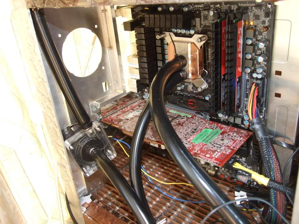
Yesterday morning it was stabilised idling at 24-26c. During the afternoon it was very hot in my room (faces the sun and has a large tropical fish tank in - ambient was around 30c I expect) and was idling at 34-35c. Load temps were 62c in occt and 70-72c using Intel Burn Test on maximum stress. That's with 9w ddc with ek v2 top, radiator case, heatkiller 3.0, swiftech mcw60 (not on the card though) in the loop cooling an i750 at 4GHz, vcore around 1.3-1.35 iirc.
Will need to try it with the gpu in the loop and at a higher overclock - my chip needs 1.4-1.45v to get to 4.3-4.4GHz...
I'm planning on making a 9x12cm attachment to add to the bottom to blow up through the fins. Was thinking on either sanyo denki 9s1212l401 fans if I want to pay 20quid+ a fan, or scythe gentle typhoons or yate loons attched to a simple fan controller.
Associate
have you thought about chrome plating it would look amazing
I would love to know what flow rate you've got going with a 9W (10W?) ddc in there.
If you wanted you could fit one of those mini fillport res's to the top plug via a nipple fitting. That would at least tell you the water level is where it should be. You might have to make an additional mesh top cover to hide it though as it would stick out a bit and be vulnerable to knocks.
How much water did you put in it?
Associate
wo0t wo0t
Nearly done :O
Nearly done :O
- Joined
- 13 Mar 2006
- Posts
- 6,712
I would love to know what flow rate you've got going with a 9W (10W?) ddc in there.
If you wanted you could fit one of those mini fillport res's to the top plug via a nipple fitting. That would at least tell you the water level is where it should be. You might have to make an additional mesh top cover to hide it though as it would stick out a bit and be vulnerable to knocks.
How much water did you put in it?
It was getting 1.87gpm with an xspc edge rather than the heatkiller 3.0 in the loop with 2m of 1/2" tubing in an open loop without the mcw60 filling a 5gallon barrel. The hk3.0 is slightly more restrictive and there's the mcw60, but it has about a metre less tubing now and is a closed system now. So flowrate should still be pretty good.
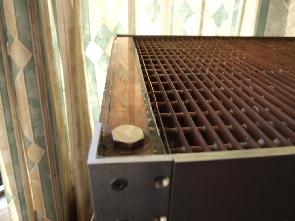
It holds just over 1.7l - the case holds 1.7l + what's in the tubing.
Sooo is the whole case watercooled? This must weigh a ton?!
It weighs around 34kgish with everything in.
wo0t wo0t
Nearly done :O
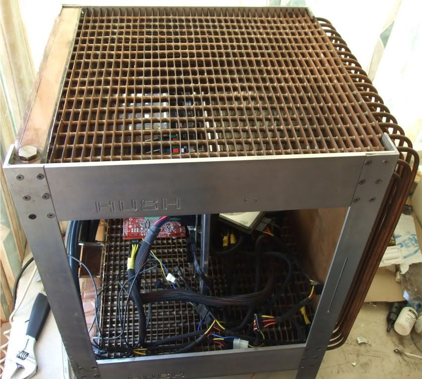
still a fair bit to do - lots of odds and ends; holes for switches, usb, firewire panel, 9x12cm fan add-on and smoked acrylic windows to keep the air going through the top fins, probably a replacement aluminium plate for the mobo tray without the fan hole, caster attachment plates, lots of sanding, attaching casters, anodising the aluminium.
It's all plumbed in atm to check it's water-tight and what temps are like.
- Joined
- 13 Mar 2006
- Posts
- 6,712
I don't know much about WC but wouldn't you need a more powerful pump? Or 2?
No, shouldn't need any more. Flow-rate is likely around 1.5 gallons/minute with the ddc. Anything over 1 gallon/minute is good, generally. It's a case of diminishing returns - at 1 gallon per minute you get around 90% of the performance from radiators and blocks IIRC. Might be slightly different for my case - will have a think about it later.
For reference with a single PA120.3 radiator it would get around 1.7gallons/minute ish I expect.Might have a tinker with a laing D5 or DDC 18w and see how they compare. Anyone fancy lending me one?

Last edited:
- Joined
- 13 Mar 2006
- Posts
- 6,712
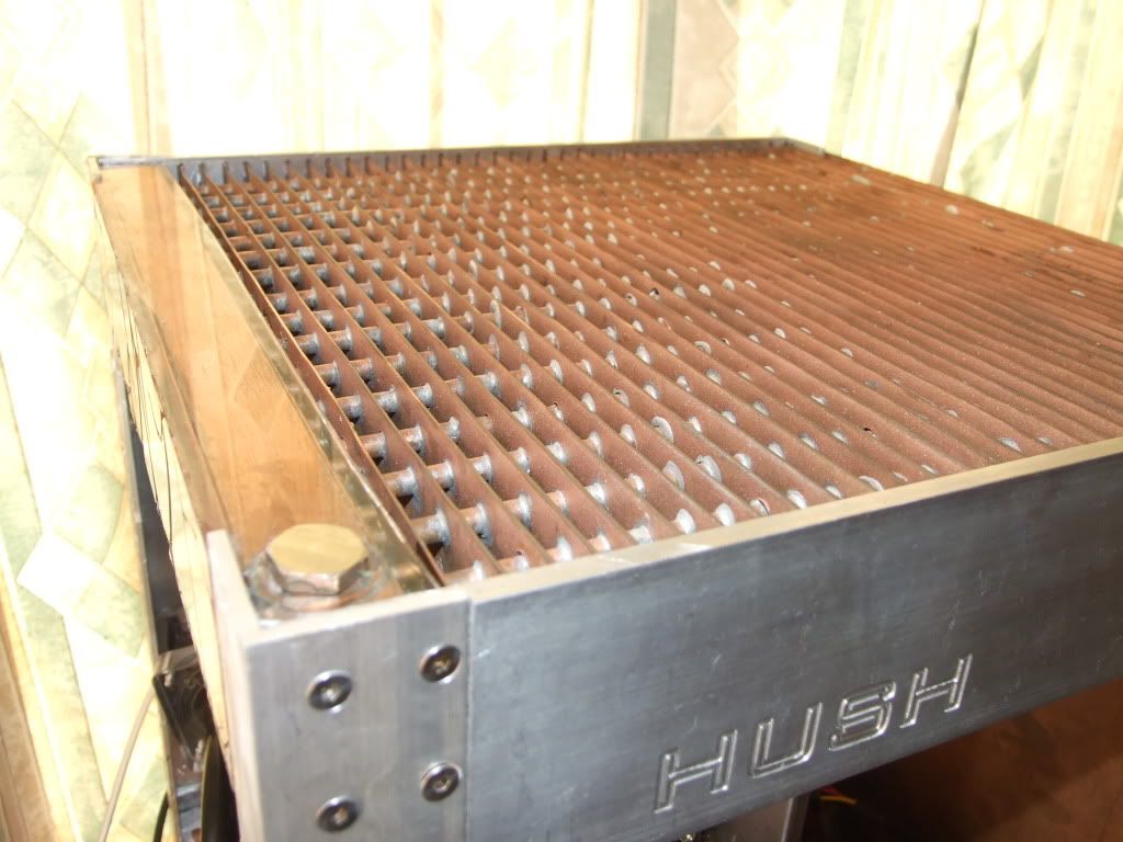
With the latest pics its easier to see that you appear to have encased both manifolds in perpex, did it develop leaks from the original manifolds after everything was put together, or is this to assist with attaching it to the frame? I guess you can paint these to hide the trapped air bubbles.
- Joined
- 13 Mar 2006
- Posts
- 6,712
With the latest pics its easier to see that you appear to have encased both manifolds in perpex, did it develop leaks from the original manifolds after everything was put together, or is this to assist with attaching it to the frame? I guess you can paint these to hide the trapped air bubbles.
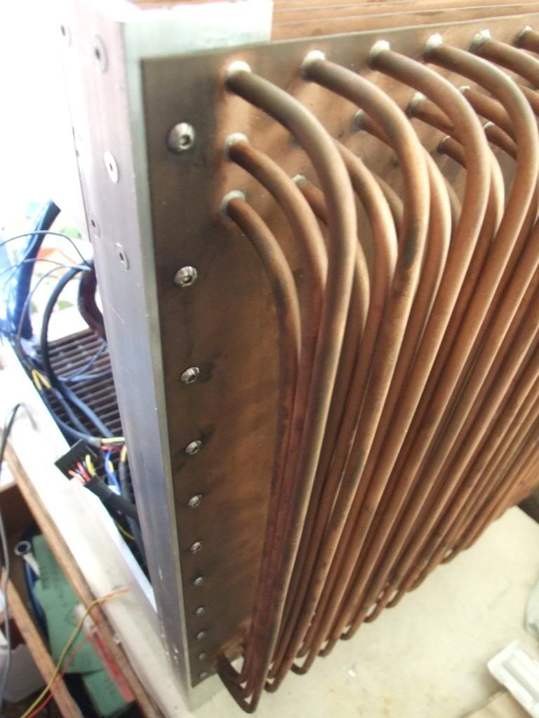
Yeah they developed leaks - the boxes had an inner thin walled copper box soldered to the end copper fins, with thicker copper plates epoxied on. But the inner boxes warped slightly and the epoxy didn't cover all the gaps so there were escape routes. It leaked very very slowly with the pump on. I had fixed it with epoxy over the outer box edges, but it looked messy and ugly, so I sanded off the epoxy over the outer edges, sanded the copper down to 1600-2000 grit, made a mold and cast clear polyester resin over it. Now looks much better and will sit flush with the aluminium frame so much tidier.
Unfortunately I made the mold from acrylic sheet and left the protetctive film on facing the resin. As the resin set it contracted slightly and pulled the film away from the plastic mold, forming very shallow (~1mm) grooves, and leaking slightly in the process, making the resin about 1mm thicker where the grooves are, so they should be able to be sanded down and polished and still sit flush with the aluminium frame.
There aren't really any bubbles, and the shiny plastic over shiny copper looks pretty on the bits of mold without protective film. Should look nice once sanded and polished down.
It's not really to assist in attaching to the frame - that'll be done by the epoxy resin going into the 3mm wide slots on the inside of the aluminium frame that each copper fin sits in, and by the 18 bolts attaching the aluminium frame to the copper back wall and also by an aluminium 1cm square cross-strut that'll help secure the mobo tray and be screwed into the frame at the front and back. It's nice and sturdy as it is atm tbh. The cast perspex does fill in the slight gaps between the copper radiator plenums and the aluminium frame, which is a plus.
Last edited:
Associate
thats pretty nuts. dont it wiegh quite a lot tho?
Soldato
Ah first i had no idea what was going on... but after looking and reading thro it... epic!
Wish i had the time to do something epic like this... Enjoy mate!
Out of interest could you not dip the whole thing in some sort of paint? or would that just keep the heat in?
Wish i had the time to do something epic like this... Enjoy mate!
Out of interest could you not dip the whole thing in some sort of paint? or would that just keep the heat in?
Associate
Out of interest could you not dip the whole thing in some sort of paint? or would that just keep the heat in?
I think he's planning on doing that later, though I may be wrong. Maybe powdercoating it, or something similar
It's nice to see this in the Project Logs!
- Joined
- 13 Mar 2006
- Posts
- 6,712
Sorry to bring this back from the dead! Any updates? I'm really looking forward to seeing the finished thing.
It's not dead! updates will be coming - without a decent camera atm - took some pics on my n97 phone but don't have the micro-usb to usb lead with me so can't upload them atm. There was a fairly nasty hiccup - the fill cap on the top had gotten some resin in the thread. I tried to get rid of it with acetone on a cotton bud and then scrape it off, but the thread got a little mangled. Then it was a nightmare to screw in the plug - it wouldn't seal unless very tightly screwed in. Then I screwed it in too tight, heard creaking, and then the copper ring/washed type port on the top shered from the solder and came off, leaving a hole and a small shard of resin came off, thought the resin top is okay. So then I defiled an old fullcover copper EK block for an x1900xt with a dremel, just to get a 1" diameter copper replacement port! Filed it down, bought an m2 countersunk drill bit and drilled and tapped 6 countersunk m2 holes for 6 screws to attach the replacement port to the copper box1mm thick top panel to resist rotational forces when screwing the fill cap in. Sorry I don't have pics - but have some very nice ones to upload!
thats pretty nuts. dont it wiegh quite a lot tho?
Yes, yes it does. About 30-35kg with everything in.
It's nice to see this in the Project Logs!
Sweet, OcUK has a modding section now!
Ah first i had no idea what was going on... but after looking and reading thro it... epic!
Wish i had the time to do something epic like this... Enjoy mate!
Out of interest could you not dip the whole thing in some sort of paint? or would that just keep the heat in?
Cheers!
I think he's planning on doing that later, though I may be wrong. Maybe powdercoating it, or something similar
Nah, no coating planned - don't want to hinder the cooling. could do with a proper clean though - the bead-blasting has only got down to about 1cm either side of the copper fin edges, so still lots of tacky burnt-on flux covering about 2/3 of the fins (but not very visible). might have to soak the whole thing in a bath of washing-up liquidy warm ater and set at it with a toothbrush or similar.
Oh, speaking of the cooling performance, I decided to attach the GPU block to the graphics card, so I drained the loop and decided to have a look inside the heatkiller cpu block, and it was almost completely gunked up - must have been the chemically melted bits of resin from the top port that came out of the thread. Of the 13 slits in the internal impingement steel insert, all but about 1.5 were completely sealed with plasticky goo and only about two 5mm thick strips were getting any water cooling at all!
Now it's been cleaned up and with the 4850 GPU in the loop as well, with the i5 750 overclocked to 4.2GHz using 1.43 vcore, it maxes out at around 55C in Intel Burn test iirc, and around max 50C in games.
Should have it up with me next weekend for good to do more thorough testing and get some pictures up.
Last edited:
Soldato
have not followed this in a while...AMAIZING