

You are using an out of date browser. It may not display this or other websites correctly.
You should upgrade or use an alternative browser.
You should upgrade or use an alternative browser.
Scratch build valve power amps
More options
Thread starter's postsI'd like to say I've been enjoying it, but it has had the effect of making me feel just a tad thick at times. Trying to get my head around some of the theory has been very difficult. Between feedback compensation, phase shifts and poles my head pretty much fell off.God I love this. Exactly the sort of project I'd have loved to get my teeth into once upon a time.
Great stuff OP
Made some more progress over the weekend. Modelled the transformer using just the signal generator through a 4.7K load across the anode connections linking the HT centre taps together and an 8R load on the secondary. Connected one channel of the scope to the primary and the other channel to the secondary and measured the time difference between the primary and secondary.
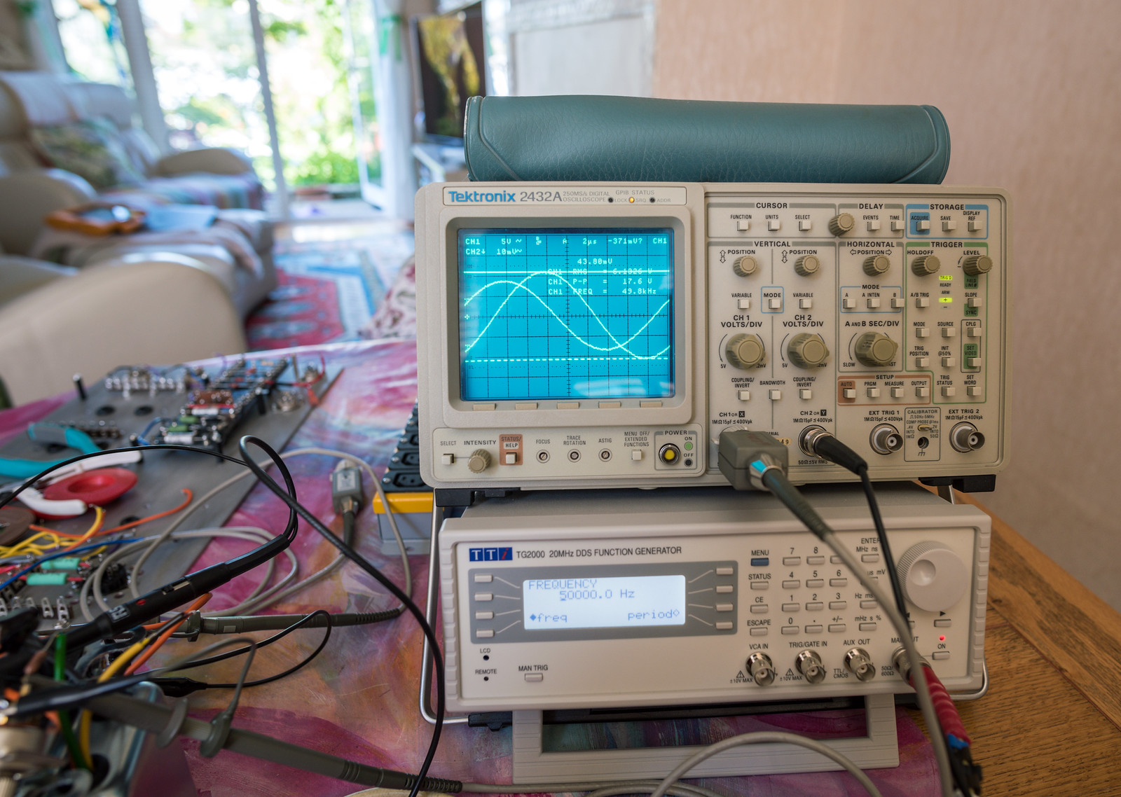
Plotted the results on a graph
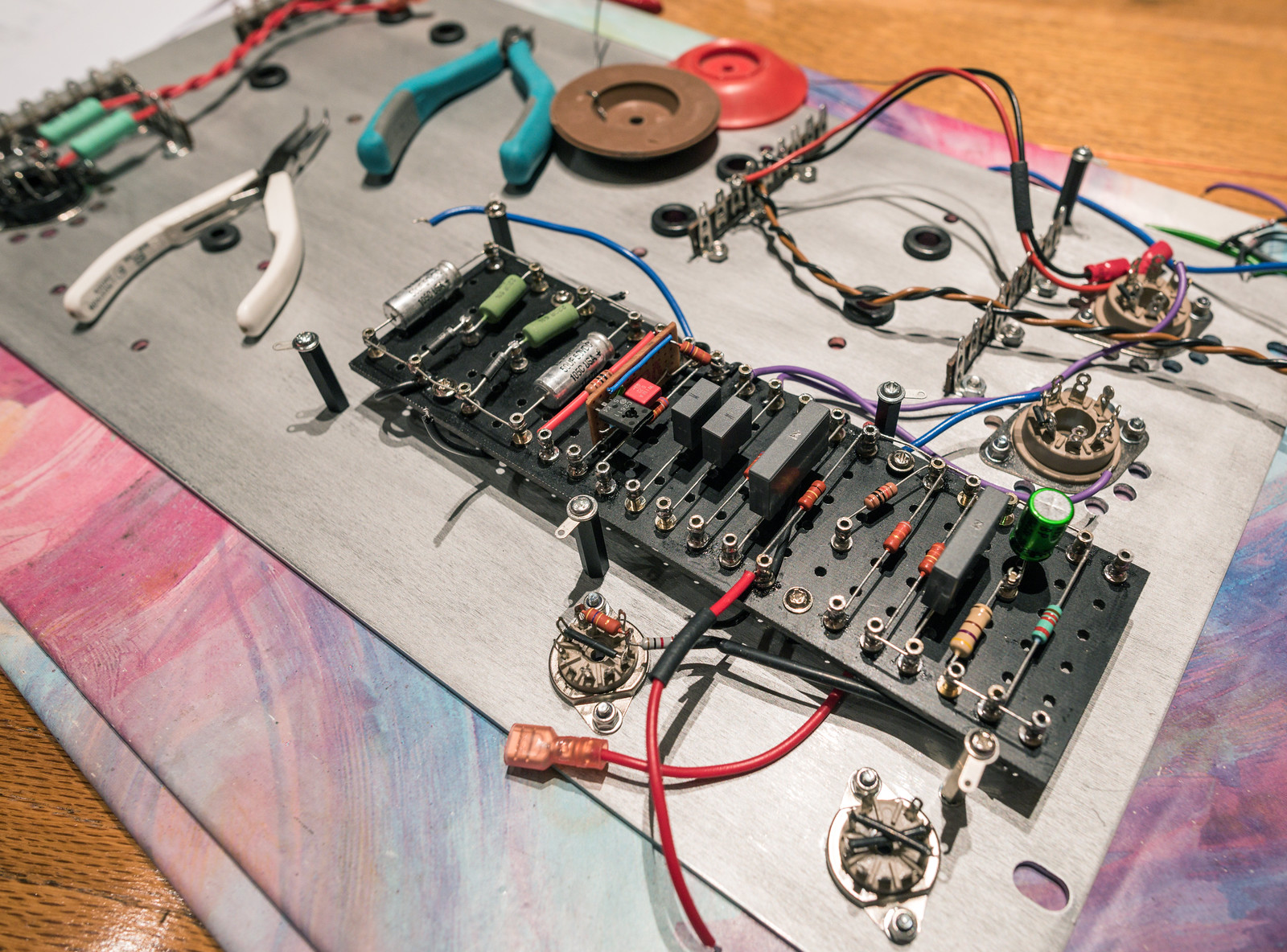
Got the constant current sink built on veroboard and fitted it to the main turret board.

Finished off all but the feedback section of the turret board today.
Soldato
Makes me quite glad I build guitar amps not hi-fi! There are plenty of imperfections and inefficiencies and downright "bad design" in guitar amps. It's what makes them sound unique and sound good. That said, my 18W push-pull EL84 amp is finished and it's too, TOO loud. Already planning out a more self-designed amp using just small pentodes for lower volume 
I'd like to say I've been enjoying it, but it has had the effect of making me feel just a tad thick at times. Trying to get my head around some of the theory has been very difficult. Between feedback compensation, phase shifts and poles my head pretty much fell off.
Made some more progress over the weekend. Modelled the transformer using just the signal generator through a 4.7K load across the anode connections linking the HT centre taps together and an 8R load on the secondary. Connected one channel of the scope to the primary and the other channel to the secondary and measured the time difference between the primary and secondary.
Plotted the results on a graph
Got the constant current sink built on veroboard and fitted it to the main turret board.
Finished off all but the feedback section of the turret board today.
That's impressive. No idea what you're on about though! I always thought electronics looked interesting but aware it's a massive rabbit hole. Looks like you're learning a lot doing it, will be very satisfying when you finally get it completed. I'm just learning about basic construction, who knew there was so much to concrete
 Your project makes me feel mine is it actually quite easy, other than feeling like I've been run over every morning!
Soldato
Impressive build and great execution. I love DIY audio, something about scratch building is daunting to me though especially valve gear. I'm sure the sound will be exquisite and can't wait to see the final form.
18W out of EL84's is pretty decent. They are usually only 10W in ultralinear, but that is with the small power losses attributed to using cathode biasing. Most guitar amps don't seem to bother with negative feedback and those that do, don't seem to use much. This has been the massive brain ache I've been dealing with. The original mullard design utilised 30dB of negative feedback which for a valve amp utilising global negative feedback is massive. Most didn't exceed 20dB.Makes me quite glad I build guitar amps not hi-fi! There are plenty of imperfections and inefficiencies and downright "bad design" in guitar amps. It's what makes them sound unique and sound good. That said, my 18W push-pull EL84 amp is finished and it's too, TOO loud. Already planning out a more self-designed amp using just small pentodes for lower volume
I certainly hope it'll satisfy once finished. It's certainly been a learning curve and far harder than I imagined it would be. At this stage, I feel I might have been better off just going to Audio Note and buying one of their kits, as it would have no doubt been easier but I'm starting to think, it may actually have been cheaper too.That's impressive. No idea what you're on about though! I always thought electronics looked interesting but aware it's a massive rabbit hole. Looks like you're learning a lot doing it, will be very satisfying when you finally get it completed. I'm just learning about basic construction, who knew there was so much to concrete
The build quality on the side of my bodgetastic chassis builds may be a tad questionable, but the electronic side of it should be to a high standard. I'm still working on a way to build a decent metal chassis. I've been working on it every now and then since starting the third build as it had sapped my enthusiasm.Impressive build and great execution. I love DIY audio, something about scratch building is daunting to me though especially valve gear. I'm sure the sound will be exquisite and can't wait to see the final form.
Currently, all the capacitors are now mounted in place and I'm battling with wiring it all back up. I had to extend some of the wiring that I cut off the transformers, which was not so fun.
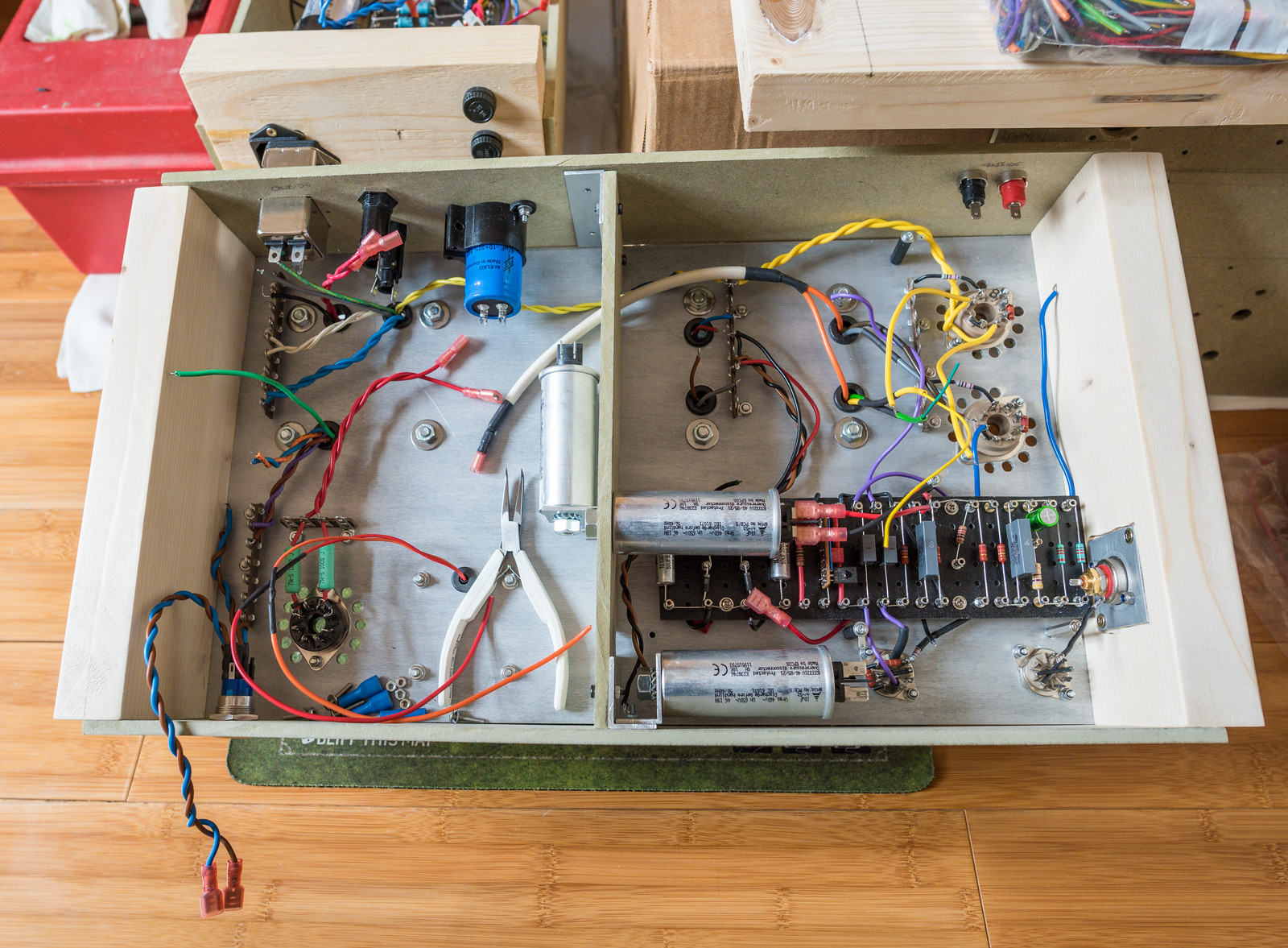
Making slow progress, mostly as I'm doing bits for an hour or so every now and then. Finished the heater wiring and the power feeds. Got to sort out the grounding and the input. Thinking of using another piece of veroboard for the input components before the valve socket to allow for the use of shielded cable for the majority of the distance.

Associate
- Joined
- 12 Apr 2016
- Posts
- 37
What a fascinating thread, so glad I found it. The specifics go way over my head, but it looks amazing.
I don't think anybody could get this far and be a tad thick. Looks like rocket surgery to me
This is the sort of thing I'd love to attempt one day. I've recently bought a valve amp for my guitar and just love hearing the hum when I switch it on. Maybe I'll make my own headphone amp one day and work my way up to a guitar head.
I'd like to say I've been enjoying it, but it has had the effect of making me feel just a tad thick at times. Trying to get my head around some of the theory has been very difficult. Between feedback compensation, phase shifts and poles my head pretty much fell off.
Same with me and opamps - I don't have a complete lack of background in electronics but I'm not that well educated in it either - whenever I think I'm starting to get my head around this stuff I run into a new concept or see someone dealing with it from another angle that leaves me feeling like a beginner.
Soldato
Professional looking chassis are the hardest thing to accomplish, I'm working on for my WHAMMY Headphone amp a case with polished aluminium, iroko wood and "forged" style carbon fibre plates that I have diy'd. with a dark greyish stain on the wood it should look nice if i can get it all together looking tight and nice fitting.... we will see though.
Professional looking chassis are the hardest thing to accomplish, I'm working on for my WHAMMY Headphone amp a case with polished aluminium, iroko wood and "forged" style carbon fibre plates that I have diy'd. with a dark greyish stain on the wood it should look nice if i can get it all together looking tight and nice fitting.... we will see though.
I've found box enclosures do some decent looking enclosures as long as you get the right panel mount connectors, etc. and have a half decent setup to drill/cut the panels, etc.
Soldato
I have always chased that premium polished product, probably why I have failed so many times. I am smitten by the idea of a completely DIY thing, the pride that is involved in it and the satisfaction that, like most audiophiles, and anyone invested in a hobby that is an endless quest for your 'your right' finds themselves chasing. I have the likes of a galaxy dissapante case like modu pioneered but something doesn't hit that spot like a custome!I've found box enclosures do some decent looking enclosures as long as you get the right panel mount connectors, etc. and have a half decent setup to drill/cut the panels, etc.
I have always chased that premium polished product, probably why I have failed so many times. I am smitten by the idea of a completely DIY thing, the pride that is involved in it and the satisfaction that, like most audiophiles, and anyone invested in a hobby that is an endless quest for your 'your right' finds themselves chasing. I have the likes of a galaxy dissapante case like modu pioneered but something doesn't hit that spot like a custome!
I got all the bits to build a balanced amp inspired by the Sennheiser Dior Homme for my HD600s but been too lazy to start on the project (house move kind of interrupted it) - I'm a sucker for a sleek black and red look.
Also built a USB powered variant of the O2 (my own design) in a 3D printed "marble" like case inspired by the looks of the original Sennheiser Orpheus amp but I kind of rushed it over a weekend and the layout didn't really come out like I was intending (though the amp performance is actually pretty good). Was more a because I can thing so probably won't go back and redo it how I'd intended it to be (as the saying goes first built a prototype because you are going to be building a prototype anyhow).

Soldato
I do like the red and black theme when done right, the Dior looks high end while being something that someone with some skill could achieve themselves. I 've never been one to work from rigid plans, I kind of see where it goes and sometimes it hits right on the spot, other, not so much.
I have to say, the WHAMMY is a piece of art, it's the first time I have felt like something deserves a home i don't just settle on, pure class A no nonsense power that drives with conviction.
I have to say, the WHAMMY is a piece of art, it's the first time I have felt like something deserves a home i don't just settle on, pure class A no nonsense power that drives with conviction.
This is very close in style to what I was aiming for at the start. I still am aiming for this as the end result. If no one has noticed, the rather horrid MDF side panels actually have an error insofar as I cut them the same length as the aluminium top plate. Head not screwed on properly at the time, but it's not final so not really all that bothered.

I've drawn up a simple veroboard for the input to the first valve grid which will allow me to use shielded cable and keep things as close to the valve as possible. The twisted wire represents what will actually be single core screened cable.

I've drawn up a simple veroboard for the input to the first valve grid which will allow me to use shielded cable and keep things as close to the valve as possible. The twisted wire represents what will actually be single core screened cable.
Soldato
This is abit out there but i think would look very nice so give it some thought, https://www.loveskirting.co.uk/skir.../solid-walnut-chamfered-architrave-sets-p2526.
Solid walnut, mitred at the ends with a nice top plate would look very nice. This is pricy but it gives you the idea.
better option for cost and similarity to your picture. https://www.loveskirting.co.uk/skir...ng-c255/solid-oak-bevel-skirting-3-metre-p412
Solid walnut, mitred at the ends with a nice top plate would look very nice. This is pricy but it gives you the idea.
better option for cost and similarity to your picture. https://www.loveskirting.co.uk/skir...ng-c255/solid-oak-bevel-skirting-3-metre-p412
That's a sound idea. Certainly easier than making it completely myself.
Finished the input board. Decided since I had some M3 threaded inserts, I'd give them a try. I had to make it a bit bigger than originally drawn as it turned out I had no low watt resistors.
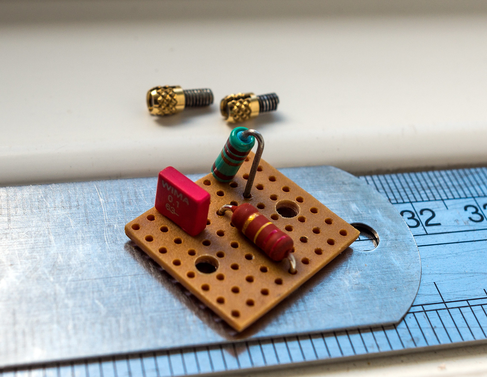
Mounted in the amp. I made a foil backed piece of card to act as a shield which I've grounded to the input socket plate. This will be linked to the ground bus. I also rotated the input valve by 180 degrees to make the control grid pin closest to the input to shorten the wiring.
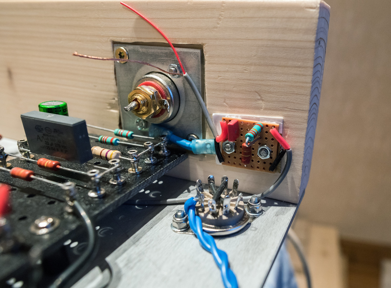
I've just got a little bit of wiring left to do before I can consider a test run.
Finished the input board. Decided since I had some M3 threaded inserts, I'd give them a try. I had to make it a bit bigger than originally drawn as it turned out I had no low watt resistors.
Mounted in the amp. I made a foil backed piece of card to act as a shield which I've grounded to the input socket plate. This will be linked to the ground bus. I also rotated the input valve by 180 degrees to make the control grid pin closest to the input to shorten the wiring.
I've just got a little bit of wiring left to do before I can consider a test run.
Finally got the MK3 prototype finished. Should be able to do some testing once I've triple checked my wiring. Everything looks good so far.

I ended up having to rotate the CCS transistor in order to fit the heat sink. Thought it best to have one as it would need to dissipate ~400mW

Decked out with valves, it definitely does look a lot better in aluminium. Just hope it performs.


I ended up having to rotate the CCS transistor in order to fit the heat sink. Thought it best to have one as it would need to dissipate ~400mW
Decked out with valves, it definitely does look a lot better in aluminium. Just hope it performs.
CCS in this case meaning constant current source. The transistor is nothing special (2SC2611), CCS describes its purpose in this particular application. It's used in the cathodes of the phase splitter which sets the bias, due to its active nature, it also helps to balance both triodes in the valve. (so the push and pull halves are equal) The more traditional way of doing this is with a resistor but that is susceptible to drift as the voltage changes.Great project!
"ccs transistor" : ccs = ?? please.