Extractor fan wiring question

Associate
Joined
28 Dec 2003
Posts
1,031
Location
Scotland / Norfolk
Afternoon all.

I have been up in my loft over the last few days dealing with the ducting in my extractor fan after discovering a small swimming pool developing up there. After much faffing with rigid ducting and insulation I hope I have sorted it out.

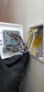
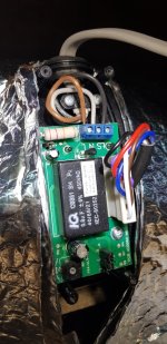
Anyway whilst I was up there I thought I'd have a look at how the extractor fan was wired up. The fan has a timer function so it should keep running for a while after the switch is turned off but this has never worked. I understand these are usually designed to be connected to the lights but I specifically asked them not to do this when they wired it up as there is nothing worse than getting up for a pee in the middle of the night and having to listen to the fan for 10 minutes afterwards! So the fan has its own switch next to the switch for the lights. However when you turn this switch off, the fan goes off immediately without the overrun. See below wiring:

Fan (can't see in the photo but terminals are marked as L / N / SL as you look at it)
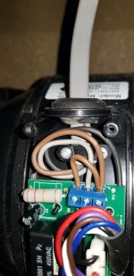
UZVxRyF.jpg

Isolator

NqGmcLM.jpg

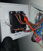
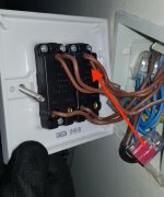
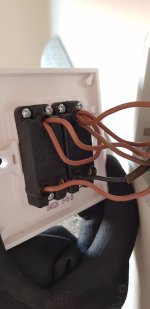
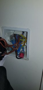
Switch (the fan switch is on the left when the faceplate is screwed into the wall and you are looking at the front of it, lights on the right)
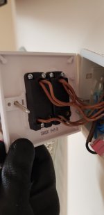
RgKlLjy.jpg

mAlh8TX.jpg

The fact this didn't work properly never initially bothered me but given the issues I've been having with condensation recently ideally I'd like to have the timer working (without connecting it into the lights so I an still use the lights without running the fan) so that it clears the ducting a bit better and hopefully reduces any condensation forming. I doubt I will be doing this myself and will get the electrician to have a look at it next time I am having work done however I am curious to understand how its been wired up and why it doesn't work as it should. Presumably it is missing a permanent live? But why? There is a black wire you can see in the photo of the wiring on the fan itself which is not connected to anything. I thought this might be a live so I tried connecting it up but nothing happened. That's probably about the limits of daft messing around with things I don't really understand that I will be doing but I am still curious to have a bit of a better understanding as to what is going on here.
 
Soldato
Joined
23 Nov 2004
Posts
3,769
When I did one last, it had a humidity setting in it so it would come on automatically when it detected any, normally not long after turning the shower on.

What make and model is it? You should be able to look up the wiring requirements online for the one you have. Was there any other switches/jumpers on the circuit board that could control the timer function?
 
Soldato
Joined
14 Jan 2018
Posts
14,719
Location
Hampshire
The extractor fan is wired incorrectly for timer function, a timer function needs Switched live, neutral and permanent live. Your has only S/L and a jumper to L so as soon as you turn off the switch the extractor isn't getting any power.
 
Associate
OP
Joined
28 Dec 2003
Posts
1,031
Location
Scotland / Norfolk
When I did one last, it had a humidity setting in it so it would come on automatically when it detected any, normally not long after turning the shower on.

What make and model is it? You should be able to look up the wiring requirements online for the one you have. Was there any other switches/jumpers on the circuit board that could control the timer function?

Its a Manrose MF100T.

The extractor fan is wired incorrectly for timer function, a timer function needs Switched live, neutral and permanent live. Your has only S/L and a jumper to L so as soon as you turn off the switch the extractor isn't getting any power.

This is pretty much what I thought. My question is why is there not a permanent live on the circuit? I thought that might be what the unconnected black wire was so I tried wiring it in but that made no difference. I suspect the black isn't connected to anything at the other end? I guess the way to remedy this would be to connect the black wire to permanent live at the other end then wire it into the fan? Or am I way off in my thinking here?
 
Soldato
Joined
13 Jun 2011
Posts
6,014
You need to find where that black is (cant see it from the pics you posted) and wire it into the ring at the switch end and into that linked terminal (removing the link) at the fan end
 
Soldato
Joined
23 Nov 2004
Posts
3,769
Its a Manrose MF100T.


This is pretty much what I thought. My question is why is there not a permanent live on the circuit? I thought that might be what the unconnected black wire was so I tried wiring it in but that made no difference. I suspect the black isn't connected to anything at the other end? I guess the way to remedy this would be to connect the black wire to permanent live at the other end then wire it into the fan? Or am I way off in my thinking here?


Hmm... looks similar on Google to the opne i installed. Are you sure there isnt a little switch or some jumpers (077548B Mixflo Fans with PCB 04-16.pdf (anda.co.uk))
 
Soldato
Joined
3 May 2012
Posts
8,611
Location
Wetherspoons
I don't t know what I'm talking about, other than their definitely should be 3 separate wires going to the fan, i redid mine not do long ago and just copied the existing wiring.
 
Soldato
Joined
10 Mar 2006
Posts
2,912
Location
Fife
You need to take a feed from one of the common terminals at your light switch and put it in with the black thats in the red wago connection at your light switch. Remove the brown link at the fan and put the black in its place.

It's not a simple mistake to make, gross incompetence from who ever fitted it.
 
Associate
Joined
20 May 2009
Posts
1,857
You need to take a feed from one of the common terminals at your light switch and put it in with the black thats in the red wago connection at your light switch. Remove the brown link at the fan and put the black in its place.

It's not a simple mistake to make, gross incompetence from who ever fitted it.

Maybe a little harsh. The OP said he specifically asked for it not to be wired to the light switch, hardly incompetence wiring out the timer function in that scenario. Maybe should haved clarified the timer wouldn't work though.

OP, you need another switch in your circuit, the isolator should stay on all the time and the link needs to be wired through a switch.
 
Soldato
Joined
18 Oct 2002
Posts
2,716
Location
Royston, Herts
Wow, whoever installed that made an absolutely pigs ear of it.
As others have said, without a separate permanent live it's never going to give you timed override. Sadly, the way they've fitted it means you've paid for the timer model but have wasted your money as they've removed that capability and, essentially, given you the basic model.
I just fitted one for a client and ran a permanent live (as part of a 1.0mm twin and earth from a lighting circuits) down to a backbox, where it splits to feed a kinetic switch (so she had the option to manually activate it) = switched live and the other side of the split remains a permanent live. Those two and the neutral get routed through the isolator (separate backboxes and the earth is connected to pass straight through with Wagos) and then they all go off to the fan.
Her fan is the Manrose MF100H (humidistat variant) so most of the time just kicks in when it detects elevated humidity and requires zero intervention from her. She only uses the switch for...odour issues , and then the timer runs for a free mins to cycle the air.
 
Soldato
Joined
9 Mar 2003
Posts
14,213
I don't see why the installer has made a pigs ear of it, its wired exactly how the OP requested it when it was installed. If you don't want the timer to run (as the OP requested), that is how you wire it.

All the wiring is there to re-instate the timer function, it all just neds to be connected up as such. It's at most a 10 minute job if you know what your doing. All that needs doing is the black wire needs hooking up at the fan and switch ends (and sleeved accordingly) and the wiring to the fan its self changing. The reason why it isn't currently live I hope is fairly obvious.

OP - if you can't work this out from the fans wiring diagram online you need to get an electrician in to sort it.
 
Soldato
Joined
10 Mar 2006
Posts
2,912
Location
Fife
OP didn't want the fan to run whilst the light was on. Not that he didn't want the timer to not run. Hence saying it's never worked right since it was installed.

So yes, not to put words in OPs mouth but I'd say he'd have wanted the timer function from the start. Thus, pig's ear.

Easy fix.
 
Associate
OP
Joined
28 Dec 2003
Posts
1,031
Location
Scotland / Norfolk
You need to take a feed from one of the common terminals at your light switch and put it in with the black thats in the red wago connection at your light switch. Remove the brown link at the fan and put the black in its place.

It's not a simple mistake to make, gross incompetence from who ever fitted it.

So like this basically?

ZQDz4FX.jpg

Regarding what was originally requested, I merely didn't want the fan to come on with the light and wished for it to be controlled with a seperate switch. I still wanted the timer to run. I obviously should've questioned this at the time but it was a couple of years ago now and I can't remember why I didn't. Had a lot going on at the time.
 
Associate
Joined
15 Nov 2005
Posts
2,307
Location
Newcastle
So like this basically?

ZQDz4FX.jpg

Regarding what was originally requested, I merely didn't want the fan to come on with the light and wished for it to be controlled with a seperate switch. I still wanted the timer to run. I obviously should've questioned this at the time but it was a couple of years ago now and I can't remember why I didn't. Had a lot going on at the time.

No you want the black wire to go into the lower terminal on your switch instead of the brown wire that's currently in there. This now becomes your switched live to the fan. The brown wire that you've removed goes to the common/constant live on you're switch.

At the fan take out the brown link wire. Double check the fan terminals and wire it as brown - constant live, grey - neutral, and black - switched live.

Your fan will then work as you want, so it will turn on when you flick the switch on and when you turn the switch off it'll run on the timer then turn itself off.
 
Associate
OP
Joined
28 Dec 2003
Posts
1,031
Location
Scotland / Norfolk
No you want the black wire to go into the lower terminal on your switch instead of the brown wire that's currently in there. This now becomes your switched live to the fan. The brown wire that you've removed goes to the common/constant live on you're switch.

At the fan take out the brown link wire. Double check the fan terminals and wire it as brown - constant live, grey - neutral, and black - switched live.

Your fan will then work as you want, so it will turn on when you flick the switch on and when you turn the switch off it'll run on the timer then turn itself off.

So I did this, and it now works as you would expect in that when you switch the fan off it will continue running on a timer. HOWEVER, it now also runs at random with the switch off. So with the switch off it will turn itself on for about 20 seconds, then off for 10 seconds then this repeats indefinitely. Bit weird no? The only way to shut it off completely is to turn off the isolator switch. This obviously defeats the purpose of the whole thing. So I have put it back to how it was wired originally. See below for how it was wired up when this issue was happening:

Sff5OdT.jpg

zgriagt.jpg

Any ideas what is going on here?
 
Soldato
Joined
23 Nov 2004
Posts
3,769
What is that jumper at the bottom of the circuit board set to? Check online docs for the model. Maybe its got a Humidity sensor and is turning on when it detects humidity?
 
Associate
OP
Joined
28 Dec 2003
Posts
1,031
Location
Scotland / Norfolk
The jumper on the right is for the fan speed (there are 3 speeds, it is set to the highest one). The screw adjustment on the left of the circuit board is for the overrun timer adjustment and is set for the maximum time. This model does not have a humidistat. In any case even if it was a humidistat model, it still shouldn't come on with the switch turned off I wouldn't have thought?
 
Associate
Joined
15 Nov 2005
Posts
2,307
Location
Newcastle
Hmmm, it sounds like a fault with the fan, I can't think of any other reason why it would do that. Have you got a test meter? If so, check the voltages at the fan when the switch is on and off to confirm that the brown wire is constantly live and the black is switching correctly.
 
Associate
OP
Joined
28 Dec 2003
Posts
1,031
Location
Scotland / Norfolk
So, an update on this. I got back up there and tested everything with a multimeter. Live showing 240V (obviously). Switched live shows 20V with the switch off and 240V with it on. Seems correct no? Anyways, I managed to obtain a replacement fan from Manrose free of charge under warranty as the fan was also exhibiting other strange behaviour such as stalling when it had been on for a while. So I suspect it was dodgy. The new fan I have wired in and it all seems to be working ok so far including the timer function and no random turning on and off. Still wondering what would've been causing the issue previously with the old fan randomly running and turning itself off? I guess maybe the capacitor that runs the timer not working as it should, holding the charge for too long and then discharging at random, instead of all in one go? Those probably aren't the correct terminology but you get what I mean.
 
Back
Top Bottom