You are using an out of date browser. It may not display this or other websites correctly.
You should upgrade or use an alternative browser.
You should upgrade or use an alternative browser.
Nick's little project
- Thread starter NickK
- Start date
More options
Thread starter's postsSoldato
Also watching this with interest. I have done a lot of electronic repair but I don't think I could ever design anything myself.
Soldato
Hey NickK, I see you don't get many replies on this thread but just to say I'm thoroughly enjoying it, great info, great little project.
Agreed, i suppose it's purely down to my lack of knowledge but i like seeing pretty graphs

Thank you - I think designing and amp is a bit like keeping all the plates spinning.
In terms of difficulty, I would say each step is probably 2x the difficulty:
1. designing your own topology/design, and supporting components
2. Using a known topology, and supporting components (but still having to work out the component values)
3. Using a known design with values
4. Using PCB unpopulated (as components you may have vs the designer vary)
5. Using pre-build PCBs as separate components assembled together
6. Buying it
So initially I was trying 2, then to 1, now I'm back to 2/1 (ie switching out the 12AU7 for 12BH7).
The current focus is on the power supply
* EMI choke - filter out the EMI from the mains and prevent EMI going back out.
* Transformer
* inrush protection
* regulation
* current limit
* 'soft' start for the amp.
An A class OTL is at max 50% efficient, and being OTL... that takes a nose drive. With the available non-custom you're looking at 100W transformers, but using a separate transformer for heaters may work out better. Although I can operate the heaters at 6.3 or 12.6V I want to limit the current flowing around the amp - current induces electromagnetic fields thus interference and noise.
Starting an amp in the old days.. literally they used valve rectifiers (with 100+V drop!) and that too a few seconds to ramp up voltage. The down side is bad current handling (sags) and it doesn't like driving large smoothing capactors.
Start up therefore now needs a couple of things in my view to design in extra; some caused by the more hard 'start' of silicon.
* Mute - this is more than a simply noise prevention (whistling etc), as the sim at startup sees a voltage peak of 90V on the rail before the output cap.. which means a spike out to both the headphones and through the feedback hitting the resistor and makes the grid of the front end go positive by about 20V it's a few milliseconds. The cathode then raises as it biases and the 20V positive, it then gets it's act together.. and it's then stabilises over then next few seconds. So a mute on the input and output would means a clean startup.
* Grid - this needs to be negative to the cathode for the tubes I have on startup.. or the tube will suffer a full power surge.
* Heaters - the euro-tubes can suffer from what looks like a white hot section of element, as the heaters are hit instantly. A cold heater starts at low resistance and then as it heats it reaches it's operating resistance. So that's a high current surge through the heater wire. Not good for the tube, so a small 'soft start' of restricted current will allow the heater filament to handle the current without a surge. Once running the circuit can be switched out.
Inrush
A thermistor works presents a resistance, that resistance causes heat and as it heats the resistance drops and more current flows. Great. However in the scenario that the power is cycled when the thermistor is hot.. you have a full current surge. So I think the way I will do that is have a relay to short the thermistor out once running. That way the thermistor cools and any power cycling will be protected.
* voltage regulation
I'll probably use a mosfet as a voltage regulator, if I need more current then I can use a combination of solid state. If I can get down to the milli-volt ripple I will be happy. The mains power can vary ±10% from 230V, so in an unregulated amp, everything then follows that continuous varying 'float'.
Now in the past I through - more capacitors the better to prevent ripple. Well that works but is a little heavy handed. Valves are VOLTAGE rather than current driven devices, so regulation makes sense and enough capacitance to smooth ripple - and this is a headphone amp!). Little point in having a mass of capacitors if they're slow in providing power. Yes this design is more current focused than normal valve amps (think tens of mA but hundreds of volts) in that each ecc99 triode will drive 60mA max.. which is quite a bit for a small tube (6AS7 and the bigger power tubes will do 110mA+ each triode). I'm essentially using input tubes (12BH7 which is a more current orientated mini-driver but linear) and a driver tube (ecc99) rather than an output tube (the 6AS7 was made to be a power regulator current bypass tube.. but became an audio 'power' tube).
* current limit.
The design originally had a CCS (a current limiter) on the cathodes. That works when the current is only drawn through it - however this an OTL. So there is a link from ground to the cathode - and that is the via the headphones. So you can limit the CCS to 75mA but if you open up the valves (bias etc) there is a scenario where you can draw 3x60mA through the headphones and max out the output tubes causing damage across the board..
Instead I'll install a CCS on the TOP in addition. This means the maximum current being able to be drawn will be limited to 75mA - the bottom ensures a flat load line thus low distortion but the top is simply set as a safety limiter. Only thing is that a IXCP needs about 5V or so to operate - this means the B+ needs to be 155V rather than just 150V.
So the experience I'm looking for is press the power.. let the power button led flash as it starts up (ie going through the steps).. then the power button led goes solid... under the hood there's lots of thinking..
In terms of difficulty, I would say each step is probably 2x the difficulty:
1. designing your own topology/design, and supporting components
2. Using a known topology, and supporting components (but still having to work out the component values)
3. Using a known design with values
4. Using PCB unpopulated (as components you may have vs the designer vary)
5. Using pre-build PCBs as separate components assembled together
6. Buying it

So initially I was trying 2, then to 1, now I'm back to 2/1 (ie switching out the 12AU7 for 12BH7).
The current focus is on the power supply
* EMI choke - filter out the EMI from the mains and prevent EMI going back out.
* Transformer
* inrush protection
* regulation
* current limit
* 'soft' start for the amp.
An A class OTL is at max 50% efficient, and being OTL... that takes a nose drive. With the available non-custom you're looking at 100W transformers, but using a separate transformer for heaters may work out better. Although I can operate the heaters at 6.3 or 12.6V I want to limit the current flowing around the amp - current induces electromagnetic fields thus interference and noise.
Starting an amp in the old days.. literally they used valve rectifiers (with 100+V drop!) and that too a few seconds to ramp up voltage. The down side is bad current handling (sags) and it doesn't like driving large smoothing capactors.
Start up therefore now needs a couple of things in my view to design in extra; some caused by the more hard 'start' of silicon.
* Mute - this is more than a simply noise prevention (whistling etc), as the sim at startup sees a voltage peak of 90V on the rail before the output cap.. which means a spike out to both the headphones and through the feedback hitting the resistor and makes the grid of the front end go positive by about 20V
 it's a few milliseconds. The cathode then raises as it biases and the 20V positive, it then gets it's act together.. and it's then stabilises over then next few seconds. So a mute on the input and output would means a clean startup.
* Grid - this needs to be negative to the cathode for the tubes I have on startup.. or the tube will suffer a full power surge.
* Heaters - the euro-tubes can suffer from what looks like a white hot section of element, as the heaters are hit instantly. A cold heater starts at low resistance and then as it heats it reaches it's operating resistance. So that's a high current surge through the heater wire. Not good for the tube, so a small 'soft start' of restricted current will allow the heater filament to handle the current without a surge. Once running the circuit can be switched out.
Inrush
A thermistor works presents a resistance, that resistance causes heat and as it heats the resistance drops and more current flows. Great. However in the scenario that the power is cycled when the thermistor is hot.. you have a full current surge. So I think the way I will do that is have a relay to short the thermistor out once running. That way the thermistor cools and any power cycling will be protected.
* voltage regulation
I'll probably use a mosfet as a voltage regulator, if I need more current then I can use a combination of solid state. If I can get down to the milli-volt ripple I will be happy. The mains power can vary ±10% from 230V, so in an unregulated amp, everything then follows that continuous varying 'float'.
Now in the past I through - more capacitors the better to prevent ripple. Well that works but is a little heavy handed. Valves are VOLTAGE rather than current driven devices, so regulation makes sense and enough capacitance to smooth ripple - and this is a headphone amp!). Little point in having a mass of capacitors if they're slow in providing power. Yes this design is more current focused than normal valve amps (think tens of mA but hundreds of volts) in that each ecc99 triode will drive 60mA max.. which is quite a bit for a small tube (6AS7 and the bigger power tubes will do 110mA+ each triode). I'm essentially using input tubes (12BH7 which is a more current orientated mini-driver but linear) and a driver tube (ecc99) rather than an output tube (the 6AS7 was made to be a power regulator current bypass tube.. but became an audio 'power' tube).
* current limit.
The design originally had a CCS (a current limiter) on the cathodes. That works when the current is only drawn through it - however this an OTL. So there is a link from ground to the cathode - and that is the via the headphones. So you can limit the CCS to 75mA but if you open up the valves (bias etc) there is a scenario where you can draw 3x60mA through the headphones and max out the output tubes causing damage across the board..
Instead I'll install a CCS on the TOP in addition. This means the maximum current being able to be drawn will be limited to 75mA - the bottom ensures a flat load line thus low distortion but the top is simply set as a safety limiter. Only thing is that a IXCP needs about 5V or so to operate - this means the B+ needs to be 155V rather than just 150V.
So the experience I'm looking for is press the power.. let the power button led flash as it starts up (ie going through the steps).. then the power button led goes solid... under the hood there's lots of thinking..
I'm starting to feel a lot more confident around the design of the power. There's quite a bit of playing you can do with respect to power supplies. For example chaining 230V -> 24V -> 230V etc so it may be better running 230 -> 24V -> 180V & 220V, the 24V is high current! You don't need exact matching transformer taps (although it helps).
So to make a flexible power supply sounds more complex than I think it is:
Let me break this into three sections:
Section 1: 230V mains -> Combo fuse + hard power + EMI filter -> soft power switch -> transformer
So this means when you switch on the hard power, it's still powered down. When the soft power triggers, only the transformer sees inrush (they're build for it). I could add a thermistor here but it's probably not required.
Section2: transformer -> rectifier + current limiter -> smoothing caps -> power relay
So this section, once the section one soft power starts, sees an inrush into the smoothing caps, however the current limiter keeps the operational limit of current to normal levels. This limiter then means there's no inrush.. just the same maximum current as if in normal operation. I'll use a power relay so that the inrush doesn't then carry through the rest of the amp.
So the caps are charged, then it's time to soft start the amp.
Section 3 - heaters: power relay -> thermistor (or solid state limiter) -> voltage regulator -> tube heater filaments
So this means that the heaters have chance to get a few seconds of ramp up before the HT is switched on. As the tubes only conduct above a certain temp, this could mean random conductivity. If it's already hot you know the behaviour. Only a couple of seconds delay but enough. As we're using a regulator on the B+ high voltage, we can't have the heaters randomly floating without causing possible noise or worse.
The heaters get a smoothed power supply but then the caps need to be able to provide the current required. I don't need todo this but I figured it's more complication not to.
Limiter over-current detection - the amp could be made to shut down (soft power switch) should a high current be detected (indicating a short).
The heater relay can then also trigger the other B+ relays:
Section 3 - B+ power relay -> voltage regulator -> 200V B+ for front end tubes
Section 3 - B+ power relay -> voltage regulator -> 150V B+ for output end tubes
So with this I have two voltages being regulated, but they're both fed from a protected common set of smoothing capacitors. The regulator provides a final smooth. I thought about having dropper resistors, but my higher voltage would be at the other end of the chain, the current hungry monsters would be before it.. so it's very likely that the voltage would vary.
Second 4 (I lied) - mute relays on the input and output signal path.
These are connected so that on startup the system is muted, but on once all the amp is operating, the mutes are disabled.
This is power setup is complicated but it's also modular. It means I can switch out sections or bypass them as I change the amp. I know two areas that could drive this:
* cascode - this needs elevated supplies and also heater supplier for the upper cascoded tubes.
* push pull - this needs B+ and B- supply rails for example.
* change of tubes - change the voltage from the regulator.
* change the power delivery - I could use say 50V 10,000uF caps by converting from 230V to 24V (50A for example) and then paralleling the caps. I can then simply step up to any voltage and then regulate.
All depends.. but for now keeping it modular means each section does its bit.
In the old days the power supply would slowly ramp up voltage until it hit a specific level (and a cap is charged) which then unmutes the output relays. The valves can cope with it. Safety was - well if it shorted it blew a fuse and the sections were isolated by interstage or output transformers.. and a general disregard for the human..
I now have a block diagram. It looks more complex than it is. I've also thought in how I can make a pure-digital DSD512 output 
I've also been looking at high voltage regulators, the difficulty is that most HV regulators for tube amps only handle ~50mA. Which is normally enough for a couple of tubes.
Interesting links for those following:
* Simple starter: https://www.electronics-notes.com/a...onics/linear-psu-series-regulator-circuit.php
* https://audioxpress.com/article/t-reg-a-high-voltage-regulator-for-tube-amps
* Broskie's article is good: https://www.pearl-hifi.com/06_Lit_A...ers/Broskie_John/HV_Regulator_OP27_IRF820.pdf
The Broskie regulator is good, it's a floating design (ie the 5V but sitting at 300V!) and uses the AC heater power line to shore up the B+ line.
I will need to adjust it, given I have two B+ lines and a heater line of 12.6V not 6.3V that will be DC.
Also on my hit list of research is SCR crowbars. The purpose for these is to detect over-voltage and simply short circuit the power. Faster than a fuse. I will put the SCR on the headphone side of the output caps, the SCR is then tied to the main transformer fuse. If the headphones get over a certain voltage the SCR shorts the transformer mains fuse and short the entire system to ground. Naturally a nuclear last resort. However I will also have current limiters anyway and positive-cathode bias for startup. This means if the power goes over 1.5V for example.. there's a problem and POP the headphones are shorted out from the supply. Not sure if it would like plugging of headphones.. so.
There's probably about 12-15 block types - sounds complex but they could be as simple as a zenner or a relay. Also not all of them are needed from day 1.
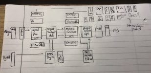
Day 1 would be:
* EMI (fuse inbuilt)
* hard power switch only
* Soft Start Current limit - stops the big 'hum' when you turn on the power, it should also mean the power comes up a little less abruptly.
* Tran + output fuse
* Caps
* Volume
* Input section + CCS
* Output section + CCS
* Output section B+ current limit (as OTL B+ has lower CCS and from headphone) - although on start the mute means the current is limited from the CCS already
* Output Caps
* Mute relay
Initially I'll not be plugging in my headphones but first a 32ohm resistor then a pair of 32ohm speakers (ie the £5) which have similar power characteristics.
Day 2
* Voltage regulators - improves noise and hum, with a 1ohm sense resistor these can also regulate current.
* delayed start bias offsetting (ie stops the grids from being wide open at 0V on B+ start for maximum current!)
* SCR
* automated startup - this performs the steps with isolated relays switching and provides a soft start button.
Day 3 - Digital
* Source/drive selection
* Digital DSD signal injection into the output section
* Digital DSD reconstruction filter switched in before the output caps.
The idea is that rather than use a balanced output from a DAC, instead the digital signal is fed straight into the output section grid. So the output switches either on or off only (no signal amplification). The reconstruction filter then sums the pulses and filters out the 24MHz switching speed. A Volume on the output is then needed but by that stage I may make a digital volume control.
The beauty of this is I can set the grid voltage for 1 and 0 separately so I get a symmetrical output.
Only issue here is that each valve triode has its own variation, so this needs exploring further, or at least average it - the beauty is it only needs 0 and 1 output so the tubes don't have to match up much.
I will have to see of the ecc99 can cope with ~25MHz signal or if it has problems.

I've also been looking at high voltage regulators, the difficulty is that most HV regulators for tube amps only handle ~50mA. Which is normally enough for a couple of tubes.
Interesting links for those following:
* Simple starter: https://www.electronics-notes.com/a...onics/linear-psu-series-regulator-circuit.php
* https://audioxpress.com/article/t-reg-a-high-voltage-regulator-for-tube-amps
* Broskie's article is good: https://www.pearl-hifi.com/06_Lit_A...ers/Broskie_John/HV_Regulator_OP27_IRF820.pdf
The Broskie regulator is good, it's a floating design (ie the 5V but sitting at 300V!) and uses the AC heater power line to shore up the B+ line.
I will need to adjust it, given I have two B+ lines and a heater line of 12.6V not 6.3V that will be DC.
Also on my hit list of research is SCR crowbars. The purpose for these is to detect over-voltage and simply short circuit the power. Faster than a fuse. I will put the SCR on the headphone side of the output caps, the SCR is then tied to the main transformer fuse. If the headphones get over a certain voltage the SCR shorts the transformer mains fuse and short the entire system to ground. Naturally a nuclear last resort. However I will also have current limiters anyway and positive-cathode bias for startup. This means if the power goes over 1.5V for example.. there's a problem and POP the headphones are shorted out from the supply. Not sure if it would like plugging of headphones.. so.
There's probably about 12-15 block types - sounds complex but they could be as simple as a zenner or a relay. Also not all of them are needed from day 1.

Day 1 would be:
* EMI (fuse inbuilt)
* hard power switch only
* Soft Start Current limit - stops the big 'hum' when you turn on the power, it should also mean the power comes up a little less abruptly.
* Tran + output fuse
* Caps
* Volume
* Input section + CCS
* Output section + CCS
* Output section B+ current limit (as OTL B+ has lower CCS and from headphone) - although on start the mute means the current is limited from the CCS already

* Output Caps
* Mute relay
Initially I'll not be plugging in my headphones but first a 32ohm resistor then a pair of 32ohm speakers (ie the £5) which have similar power characteristics.
Day 2
* Voltage regulators - improves noise and hum, with a 1ohm sense resistor these can also regulate current.
* delayed start bias offsetting (ie stops the grids from being wide open at 0V on B+ start for maximum current!)
* SCR
* automated startup - this performs the steps with isolated relays switching and provides a soft start button.
Day 3 - Digital
* Source/drive selection
* Digital DSD signal injection into the output section
* Digital DSD reconstruction filter switched in before the output caps.
The idea is that rather than use a balanced output from a DAC, instead the digital signal is fed straight into the output section grid. So the output switches either on or off only (no signal amplification). The reconstruction filter then sums the pulses and filters out the 24MHz switching speed. A Volume on the output is then needed but by that stage I may make a digital volume control.
The beauty of this is I can set the grid voltage for 1 and 0 separately so I get a symmetrical output.
Only issue here is that each valve triode has its own variation, so this needs exploring further, or at least average it - the beauty is it only needs 0 and 1 output so the tubes don't have to match up much.
I will have to see of the ecc99 can cope with ~25MHz signal or if it has problems.
Last edited:
This is what I have in mind for the digital day 3 - just using a single ecc99 here but this is the full output section:
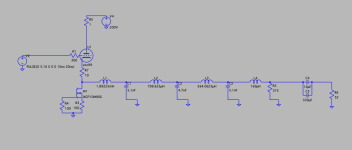
Sim wise this looks like it could work. However reality may prove more problematical.
I'd clock and pulse the signal then ping it over a galvanise isolator to the valve grid. The large number of coils after is a filter that converts the 10nS pulses to a DC level.. the DSD512 encoding then makes that rise and fall in a standard sine wave. The sim shows this works, just a little slow!
Last edited:
I think the initial voltage regulators will simply be a "maida" implementation. You loose at least 20V in the drop but basically it's a cheap starting point AND being a series regulator I can current limit at the same time.
A ON FQPK3N60C MOSFET (80p) will do 600V 3A (or 1.8A at 100degC) peak. Looking at the specs this will do DC (ie continuous) 200V (400mA) and 400 (100mA) without breaking sweat. With an LM317 behind it, it will give good -80dB noise voltage regulation without getting too fancy (at a later date).
That solves the voltage regulators for the front and backends but still leaves the high current low-voltage for heaters. These only need to cope with 12.6V but will need to cope with with a couple of amps each. The LM317 has a 2A limit and ideally you'd 1/2 that for comfort and low noise. I just need to build a current limiter for the heaters with a soft start option - this stops something that euro tubes and new tubes seem to suffer from - hot spots that exist in the heater filaments of the new tubes at startup (ie no resistance so the element gets a lot of current and it's uneven in it's resistances until fully working). Carlson has an example of this over on his YouTube channel.
Turns out someone has created a 500V 500mA capable HV regulator - using the Maida design but with a LT3080 and a 900V 10A capable part. I'll probably end up using that (he's had enough experience with it - it's been in design/use since 2012!).
Last edited:
Just put two voltage regs into the simulator - this includes AC and a power transformer, rectification too.
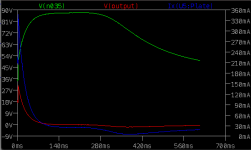
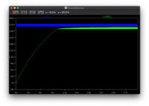
Nice soft start by the B+ voltage regs.... and see what it does.
Blue = current through ONE of the ecc99s
Green = voltage on the cathode rail
Blue = the voltage to your lovely 32ohm headphones..
Yes that's a nice starting voltage of 30V to your headphones (oh an 1 AMP) transient and an initial current of 600% through each ecc99 (they have 60mA max!). Typically this would be where the mute relays would be switched to disconnect the headphones during startup.
This is what your headphones see..
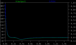
So muting the headphones during startup would probably be a good thing!
I've yet to tune the transformer or voltage regulators for the right voltage but you can see the voltage drop:
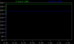
Looking at the input (yes I'm aware it's 350V!) this is the output from the transformer (blue) and the output from the full wave rectification that goes into the regulator (blue). You can see the effect that the 10,000uF cap has lol, in reality I will not be able to use that sized cap as 10KuF at 400V would be the size of a laserprinter. Instead I'll use smaller caps, but I'll have to put them in series to reduce the voltage each sees. I can then parallel them if needed to increase current and capacity. Given this is miliWatts of power.. I suspect I won't need that much.
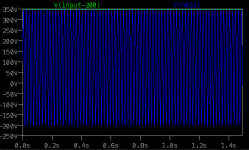
Those eagle-eyed will note the DC offset.. due to the weird transformer model setup I currently have.

Nice soft start by the B+ voltage regs.... and see what it does.
Blue = current through ONE of the ecc99s
Green = voltage on the cathode rail
Blue = the voltage to your lovely 32ohm headphones..
Yes that's a nice starting voltage of 30V to your headphones (oh an 1 AMP) transient and an initial current of 600% through each ecc99 (they have 60mA max!). Typically this would be where the mute relays would be switched to disconnect the headphones during startup.
This is what your headphones see..

So muting the headphones during startup would probably be a good thing!
I've yet to tune the transformer or voltage regulators for the right voltage but you can see the voltage drop:

Looking at the input (yes I'm aware it's 350V!) this is the output from the transformer (blue) and the output from the full wave rectification that goes into the regulator (blue). You can see the effect that the 10,000uF cap has lol, in reality I will not be able to use that sized cap as 10KuF at 400V would be the size of a laserprinter. Instead I'll use smaller caps, but I'll have to put them in series to reduce the voltage each sees. I can then parallel them if needed to increase current and capacity. Given this is miliWatts of power.. I suspect I won't need that much.

Those eagle-eyed will note the DC offset.. due to the weird transformer model setup I currently have.
Last edited:
Seems the LT3081 has a programmable current limiting on too. So I could combing the voltage regulator and current limit too! New to look at it a little more.
It can limit from 3mA upwards, so it would allow me it limit the current to something sensible.
It can limit from 3mA upwards, so it would allow me it limit the current to something sensible.
Last edited:
So looking at the power... a simplified model showing each valve as a current source simulates a valve at maximum throughput by limiting current to 100mA through each output tube and 20mA through the smaller. It occurred to me just now that the current max for an ecc99 is actually 60mA.. but I'll run that in a bit:
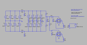
The first run looked awful - no voltage regulator.. and initially only 100uF smoothing caps with a single secondary running. I then upped the game.. making a far larger capacitance pool and had two transformer secondaries feeding current - this meant that the current draw through each cap is about 30 Amps rather than a single 60A draw previously.. Naturally - those spikes are ideally generated hence they're short spikes rather than broader smaller cycles.
Hmm started at 20V ripple.. and with caps got this down to about 1-2V..
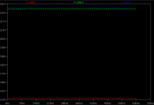
Then ... I got busy with putting a voltage regulator in.. and the ripple dropped (given this is full power running at 1A at 270V - or 270W):
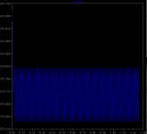
Not bad for initial attempt. 0.2V ripple. However this voltage regulator can actually do uA (micro-amp) ripple.. so I need to tweak this and get the right LTSPice models.
So now with the 60mA update, the model looks like this:
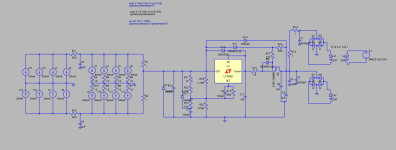
This model represents the maximum the tubes are all rated for operating (including the non-connected triodes in the second ecc99 per channel - for both channels. Total current would be 640mA but the regulator would be happy up to 1.5A.
You can see the yellow voltage regulator. This is the initial run.. If I can work out why it's messed up from a voltage perspective, then I'm laughing:

What ripple
The LT3080 LDO has a max voltage of 30V in-out but the way that the real live version of this works is to float the LDO so that it sits in a small voltage dip under the maximum voltage you set. It then works to smooth that small dip out. Hence this will work with 500V.. as long as not more than 30V is across the chip itself.
From a cost prospective, I may look at a transformer with a dual outputs - use that singularly with a a single rectifier (the 450V 4500uF electrolytic cap is £40!). Later enhancements I can update - add regulators, rectifier and cap and add a second secondary to separate the audio channels into, effectively, mono blocks

The first run looked awful - no voltage regulator.. and initially only 100uF smoothing caps with a single secondary running. I then upped the game.. making a far larger capacitance pool and had two transformer secondaries feeding current - this meant that the current draw through each cap is about 30 Amps rather than a single 60A draw previously.. Naturally - those spikes are ideally generated hence they're short spikes rather than broader smaller cycles.
Hmm started at 20V ripple.. and with caps got this down to about 1-2V..

Then ... I got busy with putting a voltage regulator in.. and the ripple dropped (given this is full power running at 1A at 270V - or 270W):

Not bad for initial attempt. 0.2V ripple. However this voltage regulator can actually do uA (micro-amp) ripple.. so I need to tweak this and get the right LTSPice models.
So now with the 60mA update, the model looks like this:

This model represents the maximum the tubes are all rated for operating (including the non-connected triodes in the second ecc99 per channel - for both channels. Total current would be 640mA but the regulator would be happy up to 1.5A.
You can see the yellow voltage regulator. This is the initial run.. If I can work out why it's messed up from a voltage perspective, then I'm laughing:

What ripple

The LT3080 LDO has a max voltage of 30V in-out but the way that the real live version of this works is to float the LDO so that it sits in a small voltage dip under the maximum voltage you set. It then works to smooth that small dip out. Hence this will work with 500V.. as long as not more than 30V is across the chip itself.
From a cost prospective, I may look at a transformer with a dual outputs - use that singularly with a a single rectifier (the 450V 4500uF electrolytic cap is £40!). Later enhancements I can update - add regulators, rectifier and cap and add a second secondary to separate the audio channels into, effectively, mono blocks

Last edited:
I did an overnight simulation, ripple wise:
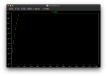
Then zooming in on the stable area:

So 263.95-263.25 = 0.7V ripple.
I R Disappoint. So there's obviously something messed up in the model for the diodes etc in use (I don't have the precise diode models etc) given the circuit has been physically built and measured at 20 microvolt ripple at 200mA 500V load (0.7V = 700mV = 700000uV vs 20uV). Also that's not all the story, looking at the FFT.. Dang that's noisy:
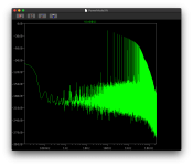
I can see a 100Hz and then images (ie replications) that go up from there - nyquist.. this looks like the switching noise (probably the noise from the 0.7V ripple itself).
As this is a single ended amp (the topology doesn't cancel/reject power supply noise) and it's a headphone amp (the output is 1V), the power supply needs to be whisper quiet.
The reason for using a regulator, other than noise, is that it allows me to reduce the smoothing capacitor size and reduce the number of secondaries in use. This voltage regulator can cope with a 20V peak-to-peak ripple and output 20uV ripple. The cost of the cheapest 4500uF 400V cap is in the region of £40-50 each. So reducing the cap size required means the regulator cost is offset by the reduction in cost..
The guy that designed this regulator back in 2012 still sells the SMD-populated board for $89CDN. It's been tried and tested by lots of audio valve guys. Add caps, fet etc to that cost. I trust his design so it's definitely my model. He's also modelled it in LTspice so..
Looking at the input from smoothing.. this looks like the model isn't even running (I get 0.7V ripple out of the smoothing caps).
Dropping down to one secondary, and only 470uF of smoothing caps gives me a output smoothing ripple of about 12V peak-to-peak. Current draw is about 0.6A -1.7A spikes. Mouser has 470uF 400V caps at £5 each (KEMET).

Then zooming in on the stable area:

So 263.95-263.25 = 0.7V ripple.
I R Disappoint. So there's obviously something messed up in the model for the diodes etc in use (I don't have the precise diode models etc) given the circuit has been physically built and measured at 20 microvolt ripple at 200mA 500V load (0.7V = 700mV = 700000uV vs 20uV). Also that's not all the story, looking at the FFT.. Dang that's noisy:

I can see a 100Hz and then images (ie replications) that go up from there - nyquist.. this looks like the switching noise (probably the noise from the 0.7V ripple itself).
As this is a single ended amp (the topology doesn't cancel/reject power supply noise) and it's a headphone amp (the output is 1V), the power supply needs to be whisper quiet.
The reason for using a regulator, other than noise, is that it allows me to reduce the smoothing capacitor size and reduce the number of secondaries in use. This voltage regulator can cope with a 20V peak-to-peak ripple and output 20uV ripple. The cost of the cheapest 4500uF 400V cap is in the region of £40-50 each. So reducing the cap size required means the regulator cost is offset by the reduction in cost..
The guy that designed this regulator back in 2012 still sells the SMD-populated board for $89CDN. It's been tried and tested by lots of audio valve guys. Add caps, fet etc to that cost. I trust his design so it's definitely my model. He's also modelled it in LTspice so..
Looking at the input from smoothing.. this looks like the model isn't even running (I get 0.7V ripple out of the smoothing caps).
Dropping down to one secondary, and only 470uF of smoothing caps gives me a output smoothing ripple of about 12V peak-to-peak. Current draw is about 0.6A -1.7A spikes. Mouser has 470uF 400V caps at £5 each (KEMET).
Last edited:
Great read - thanks for sharing
You don't need soft start with directly valves under 500v really
Regarding regs, if you can sink the heat, the salas HV v2 is incredible, you will be pushed to beat it.
I just finished a 6e6p Dr , parafeed.
IXTP08N100D2 cascade CCS.
SIC diode bias
Salas HV v2
Sound stunning , and given transformer out, can match 32, 150 and 300r headphones.
Lastly.... You sure you are going to be happy with all that hard work and then fat electrolytic cap as the last filter....thought about parafeed or even just singlend (sister?)
I’d feel safer with a a cap. The 330uF is needed to support 32ohm low frequency, the bypass 10uF shows a good frequency response.
The Thermistor is my first step and that will do for the short term but I’d like a soft start. The issue of the LT3080 is down to the junction mosfet and bad model but I’m open for any regulator initially as long as it can cope with the current demands of OTL low impedance - this has been the problem with other regulators.
There’s an interesting differential parafeed 1/2 way down the page: https://www.tubecad.com/2014/09/blog0308.htm
The first step is getting the amp up and running. I nearly have the BOM - OTL calls A means I’ll be looking at - quite a large transformer:l:
8*60mA*150+ 8*20mA*200 = 72W + 32W = 104VA just for the signal.
4*400mA*12.6 + 4*300mA*12.6 = 36VA heater
Last edited:
I have re read the whole thread. Love the design, it is wonderfully over the top.
The bit I can't get past is the choice of the Otl final stage. All that glass, all the design, then a fat lytic cap right at the output....sure I can't tempt you to go transformer coupled?
The bit I can't get past is the choice of the Otl final stage. All that glass, all the design, then a fat lytic cap right at the output....sure I can't tempt you to go transformer coupled?
Jesus... That's some requirement for a headamp!
My parafeed pulls 80ma @ 350v. Heaters... 1.2a if using the Russians, or d3a Germans only eat 700ma.
I may run the heaters off a 15V SMPS given some filtering/12.6V regulator it could easily take some load off.
I can reduce the power requirements as the model but I want some “tinker room” plus a few more VA is needed for headroom sees something approaching 180VA. Which is bananas


