Nick's little project

Soldato
OP
Joined
13 Jan 2003
Posts
23,666
There's a noise formula for Boltzman that basically means the more temperature and resistance the more noise is added by the resistors.

This means that even for the best resistors, the lower the resistance and lower the temperature results in lower noise. Although this is a tube amp (it's noisier than a digital system), it doesn't harm to think a little on this.

So I'm looking to:
a) identify high current areas
b) identify high resistances
c) reduce temperatures
d) select resistor types that area inherently low noise
e) don't vary in accuracy too much with temperature

So with this I select metal foil resistors. They have a low noise but cost a little more but aren't like the real low noise metal foil types (£20+ a resistor) that provide the best power handling and lower noise. This is in the region of £0.40 resistor and typically drops to £0.20 when you buy over 10. They also are far far better noise wise than carbon composite and carbon film. They have less inductance than wirewound.

As a basic starting point - exceptions aside - therefore a metal foil resistor, 1W, 500V and 1% tolerance with <50ppm/C will be our starting point. This will be overkill in stability and tolerance but our amp uses higher current tubes hence we need to double down on the power handling.

So in a tube amp the heaviest currents are across the tubes - this includes the anode resistor and the cathode resistor. Here the current is in the region of 20mA to 60mA per tube or 240mA on the rail. This means that if we can reduce the resistance, and increase the power handling (thus physically larger and so lower temp) we can reduce noise that would be added to the signal. In these areas 3W of power handling would be good to reduce noise. The irritation here is parallel resistors with 1W = higher resistance but lower per resistor current thus lower temp rise. So preference is 3W 500-700V resistor but we start seeing a 250ppm/C deviation which is ok for a tube amp but I'd like it under 100ppm/C.

To give you an idea - the cathode 450ohm resistors on the output stage see 1.1W each at max power. So we should be using 3W for this to keep the noise down. Temp variations will then cause variations in the operating point too but if we can minimise the variation that's good.

Compare that to the bias resistors - only 1/4 watt. The grid stopper resistors are really really low wattage. Both of these would be ok with 1W.

The poor input stage cathode resistors - it's modelling at 2.37W! (23mA) which is a little high (20mA should be max). So this will be special in that it should probably have paralleled 3W resistors. An alternative here is to modify the tube CCS stage a little to lower their operating points to reduce the current being allowed through.
This is all moot at the moment given I will need a variable resistor in there (a 5W job) for the tuning. My thinking here is once I have a real word working figure, I will switch out part of the resistance to a metal foil so less resistance at the variable resistor itself.

I also have a hole punch in the mail, that will allow me to cut the tube socket holes in the sheet metal. I have a flat sheet steel oven tray that is about the size I want - this I can use as a template for the prototyping. Then I can move to a case easily by simply putting the holes in and moving the components in one go.
 
Soldato
OP
Joined
13 Jan 2003
Posts
23,666
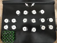
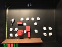
It will look something like this:
UnsoFud.jpg

The green caps at the bottom are the output caps for one channel. The output tubes (4) are behind. Centre back is the input section. Then mirrored on the other side.
 
Soldato
OP
Joined
13 Jan 2003
Posts
23,666
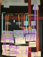
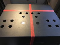
Here's the current state.. I've decided to use the hammond 14" deep x 17" wide by 5" high chassis. This may be way over kill but from others experience, it's better to go with larger than run out of room. Currently I'mm looking at this in 2D but there's some space to be saved by stacking in different orientations:

CnDJLH1.jpg

I've rotated the pan 90deg as this gives me 14" depth, I can then mark out the three red lines of - the centre line of the amp (at 8.5" wide) and then the 9" inc from the back where a hammond mesh box could sit across the amp. Behind that line is where an upper box sits that holds the vertically mounted transformer and smoothing caps.
The last red tape line is the 'quiet corridor' where large current flow and higher voltage lines are kept away from.

The red lines are the B+ lines, the cool-blue are the B- lines. The orange shows the heater lines - one at about 50V and one at about -150V to provide power - I may need another voltage level.

The violet shows the signal path flow for the both phases.

Lastly the green shows the ground line. The headphone output is for single ended (ie shared ground). If balanced output was to be used, more design work would be required - so for me this is not required.

The concept here follows:
1. the power supply is kept in the corners.
2. The input RCA, input shielded cabling, input valve and cascode sit in the quiet area.
3. The drive (DRV) valve sits just outside - this allows the power rails to be easily supplied through to the cascode.
4. The amplified output passes through the decoupling caps towards the ECC99s which sit close to the side of the case - this allows high current in wires close to the side of the case.
5. The amplified output then flows via the output caps back to the front centre.
6. The feedback is driven directly off the output caps output and then loops back via a shielded cable to the cascode.

My only concern here is that I have a large loop - as the signal return is through the centre of the amp.

In reality there's a 5" chassis depth, so I can reduce the 2D real estate by making it more 3D however that has other issues such as blocking of cooling. However I suspect that the final deployment will see the set of ecc99s move towards the centre a little.

The other point is that I have made a 'compromise' that I've switched from 3x0.1uF + 1uF for the driver coupling to simply a 1uF+0.22uF. This doesn't model much different in terms of a bode plot, it will be using the hyper fast FKP1 that has both metal foil and deposited metal plastic film in series to increase the performance (lowers ESR). Plus it reduces the size physically and with the added bonus that 0.22uF is basically the most common capacitor in the amp thus we start seeing volume cost savings being above 10 caps.

I still have to work out where I can put the variable bias pots, volume pot, muting relays.. so we're not finished yet. For example if I have the lower ecc99s closer to the back, then the dead space can be used for the bias pots.

It should also be noted that I have one input RCA or XLR balanced but a single ended output headphone jack. If I wanted to have a balanced headphone output there would need to be some additional design work (not to mention additional hardware).
 
Soldato
OP
Joined
13 Jan 2003
Posts
23,666
Next pieces of hardware ordered:
* 17"x14"x5" steel chassis from Hammond. This will end up like Frankenstein as it will be my protoyping chassis (I'll bolt new things to it as I need).
* 10x WIMA FKP1 0.22uF caps - enough for one channel, or if I decide, I can adjust and still use them if I want a larger/different cap
* 4x WIMA MKP 1uF caps - enough for both channels but I will try them in different positions - either way these will also not be unused if change things around.
* Mains, 6A IEC Socket+filter+switch+fuse all in one. Neat, clean and basically costs the same as all those parts together anyway.
* 5Watt 10K variable resistors

This will allow me to get on with the positioning, wiring.

I still need to source a toroidal transformer from the UK, but with the current delays and semiconductor/copper shortages, I would expect this to be slow.
 
Soldato
OP
Joined
13 Jan 2003
Posts
23,666
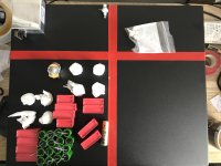
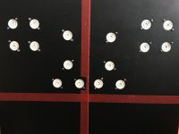
I've received the chassis and bits. I've marked up in the same way now with the real components (except tag boards, resistors, transformer etc).

vmAJHY3.jpg

There's 5" of power supply space at the back, and the idea is that the toroidal tranny is mounted vertically above the case with a second chassis will then hide the power components, a mesh front will then cover the tubes etc. Well that is the idea.

I deliberately bought a large case with some height to allow some adjustments.

F0ONfso.jpg

This would allow vertical mounting of the components - making it more compact.

I still need a few more bits but this is looking good :)

I need to get my butt in gear and source a transformer for the power.
 
Last edited:
Soldato
OP
Joined
13 Jan 2003
Posts
23,666
So I've looking into few areas:
* solder and wire - copper with silver plating 1000V PTFE wire requires a small % of silver in the solder otherwise the tin/lead or lead free will essentially strip the silver leaving no silver and so you craps up the wire. Really there's not much in terms of benefit for silver plating for skin effect with normal audio but it has it as part of the wire specification. Skin effect only starts really becoming an issue with 1MHz+ frequencies. However I have some ideas later that I may try and that would require 30Mhz.

* securing the capacitors given the number of them - I have some old but still fresh vero board I can use, I'll need to strip one strip to ensure voltage spacing and I will use wire on top but it will help keep the caps secure without stressing the pins too much. I'll mount wire as part of the strip.

* power:
In the past I've looked at large capacitors in the power supply with resistors to smooth - only issue is that a 6700uF cap rated at 450V is about £100 each. This also has some issues with increasing the inrush for the amp requiring more inrush current control or the transformer will see a straight short on the initial start until the cap is charged. The resulting output is in the order of 1V peak to peak.

I've also started looking into inductor based smoothing supplies. Two 1.5H 400V inductors (chokes) are about £15-20 for 300mA. This would use 350uF 450V caps which are £5 each. Only issue is given I now have both positive and negative rails, they both need attention.
Just to give you an example - four chokes for +/- 320 supplies would be £80. Add about £50 of caps, the resulting output is in the order of 250uV. Or 10^-6 or about -80dbV. I may be able to reduce that further but compared to the caps that's dead quiet.

I could, for either of the above, add a regulator for some additional ripple (noise) reduction. Only issue is +V regulators are easy but -V regulators seem less common. However I get more bang for my buck with the inductors.

So list of still todo:
* order wire + solder
* model and define power supply
* order transformer(s), inductors and caps
* order Omron G6A relays for muting and input select (should I want to add more than one input)
* order a volume pot (a simple pot for the initial volume control, going forward a stepped relay attenuator may be on the books).
* order mA meter for the biasing, along with the switching required..
* order the two heater transformers
* order resistors - I held off until I know the power supply completely nailed.
* tune the completed single channel
* order remaining parts for the second channel
* order chassis components including the back cover, mesh and base.
* tune
* listen

So as Kei said - his amps cost £££ due to the iron. An OTL is pretty much the same - the PSU needs more power, more tubes and more capacitors which results in the same cost but a different route.
 
Soldato
OP
Joined
13 Jan 2003
Posts
23,666
Been a little busy with the priority project (pond) over the past couple of weeks.

I've ordered some SAC035 solder from Somerset solder - it's a lead-free, RA 3.3% rosin flux with 3% silver. Solder seems prohibitively expensive as soon as you start looking at lead-free that are proven to not end up falling apart after a few years or worse still melting on the pins of the tube through heat conduction.

The silver isn't due to 'audiophool' audio frequency but rather due to it prevents the solder from slowly absorbing or etching away any silver or gold connections resulting in brittle connections. The wire I have is simply solid copper 600V/1000V PVC red/black and green/yellow. I will order a pack of PTFE (higher melting point vs PVC for safety) the only issue is that wire also has silver coating as standard so having this solder solves the issue down the line of having brittle solder joints. The next amp will be in the MHz switching but I suspect this will have little to no effect.

The concept of 'skin effect' of wire only starts making any difference in MHz upwards range. So unless you're operating a digital signal where it may help with the square wave corner transitions but in a minute way.. there's no reason to have anything other than straight copper. For anything analogue audio frequency it's a waste unless you want different resistance or capacitance (ie record player cartridge wire).

I'll order some 18AWG too for the heater wiring - hopefully today.
 
Soldato
OP
Joined
13 Jan 2003
Posts
23,666
What todo when it's pouring and thunderstorms.. :D

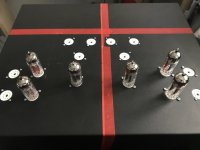
All 16 tube sockets now installed by hand using a hand drill because the drill press in the garage is blocked in by all the building crap for the pond..
nhNRxD6.jpg

If I was simply doing a single ended non push-pull configuration (as original discussed) I could simply do this:
bCTOs6i.jpg

However the V1 design is why I have 16 tube sockets.. and so the tubes will look something like this:
ASBsNOL.jpg

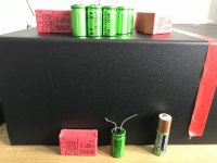
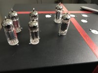
If anyone is following and wondering how the caps are going to done -

oGEyVHH.jpg
 
Last edited:
Soldato
OP
Joined
13 Jan 2003
Posts
23,666
Yep, sort of a marathon that is finally getting somewhere mixed with a lot of learning and a few u-turns..

TL;DR summary (of 9 pages):
* Class A stereo headphone tube amp with low gain for driving 32ohm headphones for CD player line in - the sound is being tuned for detail but with a little warmth of tubes (centre-warm) rather than the coldness of solid state.
* Final V1 design I settled on is split into two sections per channel - "front end" and a output section
- Front end takes a design used in the high-end Atmasphere M60, a cascode architecture and driver stages but it is modified to support using 12BH7A tubes rather than the 6SN7 tubes used in the M60. 6SN7 is a good tube but 12BH7A offers a little less tube-sound but lots of good detail.
- Output section uses a John Broskie output transformer less output (OTL) using ecc99 tubes rather than the more popular 6AS7 or 6080 tubes that are used in the M60. The big difference is the M60 uses a 'circlotron' output stage which essentially has two opposed power supplies with the speaker between them. It has no output isolation which concerns me a little for headphones so I changed the design for the output and I have isolating capacitors to prevent the possible ±200 volts from being passed through the headphone next to my ear! The output section is a 'push-pull' pairs of tubes to reduce the output impedance to get a good sound from the low impedance headphones (along with feedback etc).

A new pair of Atmasphere M60s mono blocks will set you back over $5,000 each. Mine isn't a M60 - just to be clear! So this build is a little more complex than a kits like the Bottlehead tube headphone amp. Bottlehead use two or four tubes (typically 6SN7 front into a 6AS7 output tube) whereas I'm using 16 tubes in total.. which is combination of insanity and awesomeness rather like watch makers that make complications for what is telling the time, this takes old tech and is designed to be the best it can be.

Those that aren't familiar with vacuum tubes (ie 1930s tech), they all have have identifiers like 12AU7 or EF90 etc. There's a lot of different tubes, each with their own purpose and characteristics. In short I'm using more modern tubes that are still in production, leaving the "New Old Stock" (NOS) tubes that aren't manufactured any more to those that need them. The issue is you can't simply change between them as they behave differently and need different circuits to get the best out of them so if I make something and need a new tube in years to come.. I may not find one (or they become like gold dust ££££) if I design for NOS tubes.


Just to add in terms of the thread. I'll be using Vishay Dale RN/CMF metal film resistors (also the Weleyn RC55/65 series) which give the best bang for buck without going into the audiofool unicorn resistor. I don't have many resistors in the signal path itself but this should keep the sound detailed without resulting in too much brightness appearing in the top end (resistors and other components alter the sound).

I need to get my butt in gear and order a couple of transformers.. the other life priorities have slowed progress.
 
Soldato
OP
Joined
13 Jan 2003
Posts
23,666
Update - I've been away with only a phone, paper and a pencil. That's dangerous - it leads to changes.

I've decided to improve the V1 design - if I'm going to spend £ on it then:
a) support speakers
b) support balanced output - both for speakers and headphones.
c) improve bass handling by dropping the output impedance from 12.5ohm to 0.061ohm.

Each output triode now has a BJT (solid state transistor) making it a hybrid. I still uses the ecc99 tube output but the BJT follows the output in a configured 1mA tube : 10mA BJT current output. The net effect of this causes:
a) I can supplement each triode with a 450V 30 A250W BJT providing enough current power to drive speakers
b) The BJT current handling drops the output impedance this means the bass handling of headphones and speakers is on par with solid state amps but retains the faster tube signal and harmonics - giving both current and voltage capability with the back end.

Lastly switching two two 0-200V (rather than one +200 and one -200) by switching away from the totem pole push pull to circoltron. This complicates things further - as the power supplies are floating.

So I'm modelling that backend.
 
Soldato
OP
Joined
13 Jan 2003
Posts
23,666
So "C'est Compiqué" is looking good.

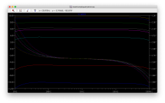
The lines on this are the frequency response across the spectrum (a bode plot) for each impedance being driven:

Az7NJo9.png

In order on the diagram:
600 - that's your studio high end headphones.. typically these like voltage (ie 4V peak) but don't take much current.
300 - again high end..
120
64
55 - this is your AGKs and the low impedance studio and cans. Typically these like around 1V but higher current.
32 - this is your harder current hungry headphones.
And just to add some spice
8 - normal 8 ohm speaker
4 - harder to drive 4 ohm car type of speakers and smaller subs.

TLDR; This can easily deafen you and drive HPs to >120dB or burn the voice coils.


The architecture on the back end has been completely replaced. Moving from the class A totem pole push-pull tube OTL output.. to a pure class A twin circlotron tube BJT hybrid.

So how does this differ from normal tube - solid state hybrids?

The easy hybrid is for a tube front end to end in a high input impedance of the solid state devices (mosfets), the SS devices then switch the power to the headphones providing low output impedance and high current handling. So the tube output never gets to the headphones - only the solid state does.

However I want the tube amp to drive and the solid state to follow, helping with current. Sort of like a super-duper power tube without the kilovolt power requirements. This is the guiding principle of the amp. The addition of parallel devices then results in lower output impedance which is good for the frequency response.

My design augments the tubes sat in a circlotron configuration (balanced bridge essentially) with solid state BJTs. The result is the current from the tube drives both the load (headphones) but through a current mirror. The current mirror then controls the solid state mirror BJT directly connected to the headphones. Thus both tube and solid state drive the headphones.


Now it's possible that the BJT NPNs in use (40V 100mA max each) could be replaced by a larger 40V 2A max. Assuming the tubes can drive them without problem, the result could drive speakers in class A with each tube then providing a maximum of ~80W.. which then leads me to the power supply.. that would then need beefing up.. given eight 80W devices would need two 40V 400W power supplies per channel.. that's 512W into 8 ohms per channel..

So you can see.. lots of flexibility. What I may do is make a 50-80W/ch into 8ohms which has more modest power supply requirements..
 
Last edited:
Soldato
OP
Joined
13 Jan 2003
Posts
23,666
So I went back to the "how to design a cascode" from scratch.. stuck to the basic 2/3 1/3 rules and the cascode was outputting OBSCENE gain. 66x ... which I was trying to avoid previously however the resulting spectrum was starting to come good.. and then it struck me - I've not added feedback in..

Without feedback.. (the front cascode is running at about 100Vpp output)
jNaUUIn.png

Connecting feedback..
43dGjW7.png

Ok I may have made the amp completely soulless with no audible distortion.. but the amp is outputting 1.5V peak-to-peak (enough to drive my headphones over 120dB) with just a 1.5V input signal :D yes.. this is acting as a unity buffer! however it's going to drive whatever you plug into it.. and the previous inputting stage will not even know..

Obscenely the same amp can push 450mA peak-to-peak (24.V peak-to-peak) into 55 ohm if I remove the feedback - and that's without running a special speaker stage.
I think I should rename this amp .. Mjölnir springs to mind. but I quite like "C'est complique", as it's subtle..
 
Soldato
OP
Joined
13 Jan 2003
Posts
23,666
Slight change of gear (speed wise) - this little baby arrived today:
QOQZ4wG.png

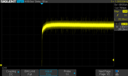
4 channel 200Mhz goodness. Although not the same as an analogue oscilloscope, it's already identified my battery charger creates a massive amount of noise. Also identified that Metalica record their CDs over the 3.16V peak consumer standard.. 3.52V measured.

I'm happy with the design now, plus the power supply. So in short I'm going to start ordering pieces starting with the power supplies.
 
Last edited:
Soldato
OP
Joined
13 Jan 2003
Posts
23,666
So I've been busy on the pond and looking for a job, but the project time has been taken up by making a software wave generator that the scope can use :D

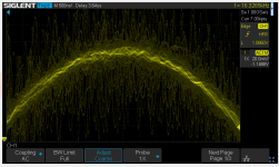
So the scope is great. This is a the sound wave at 16KHz, where I've zoomed into the top of the sinusoidal wave of that in realtime at 16KHz - it shows the noise:
xUeYrDR.png

The scope is happy doing this at 200MHz. People have measured it at 238-250Mhz.. plenty enough for scoping a digital DSD 512 signal..

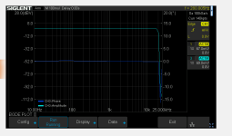
And this is the bit that I wrote.. the software emulates a abstract wave generator - so that the scope can tell the software to generate a sound through the headphone into the amp - the scope then can connect at the input and output and show the frequency response of the amplifier. The picture below shows the frequency response of the headphone jack of the Mac mini :)

9jtbmDC.png

The low pitch sound on the left, the high almost inaudible pitch to the right. You want the output to be flat across the frequency range then drop off at 20KHz to filter out any high frequency noise.

So this means I can plug the headphone jack into the input of the amp, connect a scope lead to that input, then connect a scope lead to the output of the headphone amp with the headphones attached and let it rip... it will then measure the frequency response of the tube headphone amp :)
 
Last edited:
Soldato
OP
Joined
13 Jan 2003
Posts
23,666
An update - an a little change in direction with this. I've decided to go hybrid on this but still use tubes but simplify (and make cheaper). The reality is that the old amp really did have a lot of gain in the first cascode stage.

From scratch for a balanced headphone stage
1. Use off the shelf power transformers
2. Use simple non-regulated supplies to start - a simple RC filter.
3. Target line input - so 776mV to 3.16V peak for consumer line input.
4. Low output impedance - required for driving low impedance 32-100 ohm headphones requires low output impedance.
5. With 104dB/V then realistically a clear 1V but a system that can deliver 2.5V would be useful for the higher impedance headphones.
6. The design becomes less Voltage amp and more current amp.

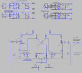
BAZRxql.png

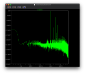
This is the result - not bad starting point from the sim:
Vu1bwBd.png

The two main areas of improvement are:
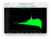
a) the 100Hz and spray of harmonics/intermodulation noise at around 150dB across the spectrum is due I suspect to the simple power filter. Upgrading with a regulator would improve this heavily. This means I should specify more voltage for the transformers (the regulators drop voltage to smooth) and in the interim simply use resistance to drop the voltage.
b) Spray of noise 100KHz+ I need to work out. I'll do this without feedback attached and see where that goes.

It's worth noting it is unlikely you will not hear below -120dB. To play 120dB would cause permanent hearing loss - then to hear a faint noise at the same time is unlikely. What it does do is cause impact on the amp.

The sim is 'ideal' and I suspect that I will need to add some DC offset balancing between the two sides.
 
Last edited:
Soldato
OP
Joined
13 Jan 2003
Posts
23,666
I've no idea whats going on here, but it looks like you are a man with mission, so keep it up! :eek:

All should become clearer as the Mrs has approved. Annoyingly the parts are becoming in short supply and on long back orders (toroid power transformers for example). The parts for this will be a little like lego in that I can try different designs. I'll reuse the case I have and the design will fit into that case, but only two tubes per side will be needed for now - and for now I will simply use one channel.

I can also then reuse the PS to test the larger design idea too. It will need voltage multiplying from 117V x 6 to get 640V for example. At the same time the current for the power supplies is divided by 6 so as long as I have enough starting current for running 640V at 20-60mA or so then that's all good (ie 60mA * 6 = 360mA minimum per 117V secondary) then I can try a second design without replacing that power supply. That second design will likely be a hybrid for speakers instead.
 
Soldato
OP
Joined
13 Jan 2003
Posts
23,666
So I've ordered the parts. It took a while to go through an change some of the parts to reduce the cost slightly. @Biffa - perhaps a little explaination.

A hybrid amp uses vacuum tubes and solid state components to amplify the sound. In my case the amplification is class A which amplifies the sound without breaking it into two halves (like AB to B class). That leads to a purer analogue sound. Next up is the design (or architecture) of the amp, the circlotron, which uses two amplifiers in opposition (kind of like a bridge amplifier) for each channel. The difference with a circlotron is that it has a requirement for a power supply floating (the PS is really part of the amp) and in the case of a hybrid circlotron it has a five power supplies per channel (two 117V, two 22V and a 12V heater supply for the tubes).

Essentially the tube amplifies the sound and the solid state component provides more current muscle controlled by the tube.

I've simulated the circuit using component models in a tool called LTspice. It basically gives a good hint at the resulting circuit - how good the sound will be if you like.

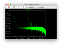
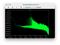
Playing a 1KHz tone through the simulator allows me to see the resulting sound from the amp:

dSnth9N.png

The dB scale on the left shows the level of the sound - this is quite quiet but loud enough for the headphones I'm using. The frequency (Hz) goes from low to high on the bottom. You can see I have a peak at 100Hz and some harmonics from that spread up the frequency spectrum. This tells me I can reduce the noise in the power supplies at a later date. The 1Khz tone is the output and the harmonics at 2KHz and 3KHz etc tell me that it has odd harmonics that haven't cancelled out (one amp and the other amp in opposition cancel out even harmonics) it will sound like a push-pull tube amp (or a solid state amp) for this reason.

DC component:-0.00147689
Total Harmonic Distortion: 0.004612%(0.004590%)

So a THD of 0.0046% is pretty good for a tube amp :) It should be clear as a bell. The DC component is important as this is a directly coupled amplifier - there's no transformer or output cap between the output and the headphone. Too much DC and it will destroy the headphones. The amp monitors the DC levels and adjusts so it's only 0.00014 Volts (1.5mV). If you're over 10mV then you start asking questions.

In reality the real amp will have less than ideal components hence it will have more noise etc but this shows it's a very good amp so far.

I may also add a tube to amplify the sound ahead of this but, this can take a line out without amplification.

I can also adapt the same design for a larger output for speakers, although typically more power results in larger THD, this should be better than my Musical Fidelity A220 by quite margin in quality of sound.
 
Back
Top Bottom